About this Document
Copyright©2011Control4.Control4,theControl4logo,the4-balllogo,theControl4Certied
logo, the Control4 iQ logo, and Everyday Easy are registered trademarks or trademarks of
Control4 Corporation in the United States and/or other countries. All other names or brands
may be claimed as property by their respective owners.
Part Number: 200-00185 Rev E 4/1/2011
Regulatory Compliance
FCC/Industry Canada
FCC ID: R33C4HC3002/Canadian IC : 7848A-C4HC300E
This device complies with Part 15 of the FCC Rules. Operation is subject to the following
two conditions: (1) this device may not cause harmful interference, and (2) this device must
accept any interference received, including interference that may cause undesired operation
of this device.
Le présent appareil est conforme aux CNR d’Industrie Canada applicables aux appareils
radio exempts de licence. L’exploitation est autorisée aux deux conditions suivantes : (1)
l’appareil ne doit pas produire de brouillage, et (2) l’utilisateur de l’appareil doit accepter tout
brouillage radioélectrique subi, même si le brouillage est susceptible d’en compromettre le
fonctionnement.
This equipment has been tested and found to comply with the limits for a Class B digital
device, pursuant to Part 15 of the FCC Rules. These limits are designed to provide reason-
able protection against harmful interference in a residential installation. This equipment
generates, uses, and can radiate radio frequency energy and, if not installed and used in
accordance with the instructions, may cause harmful interference to radio communications.
However, there is no guarantee that interference will not occur in a particular installation. If
this equipment does cause harmful interference to radio or television reception, which can
be determined by turning the equipment off and on, the user is encouraged to try to correct
the interference by one or more of the following measures:
• Reorient or relocate the receiving antenna.
• Increase the separation between the equipment and receiver.
• Connect the equipment into an outlet on a circuit different from that to which the
receiver is connected.
• Consult the dealer or an experienced radio/TV technician for help.
IMPORTANT! Anychangesormodicationsnotexpresslyapprovedbythe
party responsible for compliance could void the user’s authority to operate this
equipment.
IMPORTANT! Tousleschangementsoumodicationspasexpressément
approuvés par la partie responsable de la conformité ont pu vider l’autorité de
l’utilisateur pour actionner cet équipement.
Recycling
For information on recycling, please go to www.control4.com/recycling.
Limited Warranty
For complete warranty information, including details on consumer legal rights as well as
warranty exclusions, visit www.control4.com/warranty.
Set Up IR Emitters or IR Blaster
Your system may contain third-party products that are controlled with IR commands (usually
through remote controls). To provide a way for the Home Controller to control a device that
only recognizes IR commands, complete one of the following setups: IR Emitters or IR
Blaster.
IR Emitters
IR Blaster
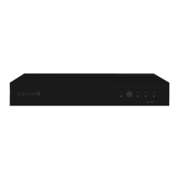
In addition to IR emitters, the HC-300 is also equipped with an IR blaster, which is located
just left of the front LEDs. To use the blaster instead of an IR emitter:
Plug the 3.5 mm connector end of one of the six (6) IR stick-on emitters provided into an
IR Out port on the HC-300.
Place the stick-on emitter end over the IR receiver on the Media Player, TV, or other
target device to drive IR signals from the HC-300 to the target.
1.
2.
In Composer, connect the Front IR Out #6 of the Home Controller to the IR In of the
device you want to control.
Do not physically connect anything to IR Out Port #6.
Test and verify that the HC-300 is positioned in such a way that the blaster can reach
the device you want to control.
1.
2.
3.
Set Up External Storage Device
You can store and access media from an external storage device, such as a network hard
drive or USB memory device by plugging the USB drive into one of the USB ports and
congureorscanthemediafromComposer.
Troubleshooting
Factory Restore Button
To restore the HC-300 for system recovery to the factory default image, on the back of
the device insert the end of a paper clip into the small hole (to the right of the Audio In
jacks).
Power cycle the device while pressing and holding the Factory Restore button. After
about 5 to 7 seconds, the Status LED starts blinking orange to indicate the start of the
recovery process. After the Status LED stars blinking orange, you can release the
button.
1.
2.
Identification Button
To reset the HC-300 to the network defaults, on the front of the device power cycle the
deviceandholdtheIdenticationbuttonuntiltheData,Link,andPowerLEDsaresolid
blue; immediately release the button.
Ifduringthebootsequence,theStatusLEDstaysOrange,pressandholdtheIdentica-
tion button until the LED blinks Blue, and then release it.
1.
2.
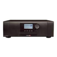
Figure 1. Contact Port for Voltage Source (e.g., Motion Sensor)
Figure 2. Contact for Dry Contact (e.g., Door Contact Sensor)
Figure 3. Contact for Self-Powered Voltage Source Device
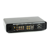
Figure 4. Relay Port: Normally Open
Figure 5. Relay Port: Normally Closed
Connect to the Relay Port
The HC-300 provides one relay port as a subset of the pluggable terminal block provided.
For most applications, attach one wire to the common terminal and the other to the normally
open terminal. The relay switches closes when the relay is activated. The HC-300 can sup-
port applications that require a normally closed contact.
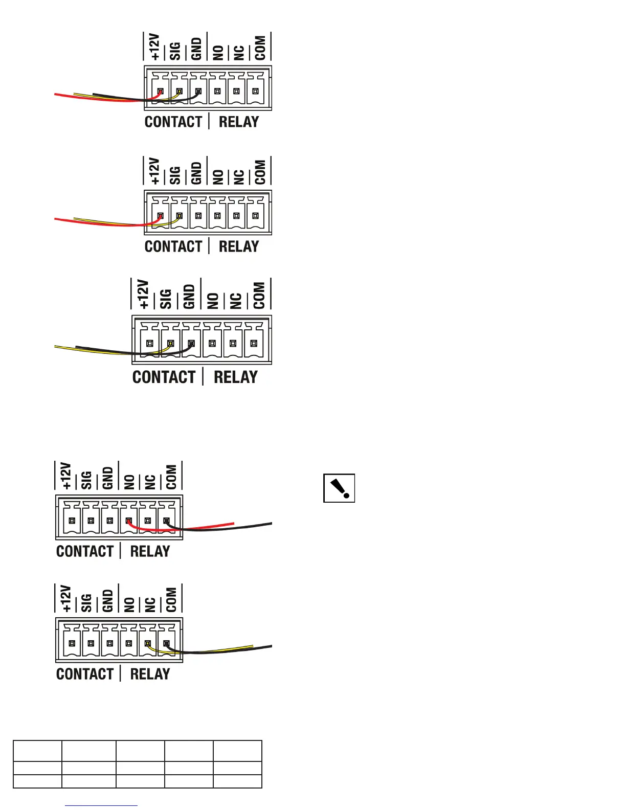
Connect the Serial Ports
The HC-300 provides two (2) DB9-style serial ports. Connect a device to the HC-300, like a
receiver or disc changer, by aligning the pins and tightening the screws. See the table below
for serial communication values.
Hardware
Flow Control
Odd Parity Even Parity No Parity
Serial Port 1 X X X
Serial Port 2 X X X X
Australian/New Zealand
• AS/NZS 4268:2003 + A1:2005 & A2:2006.
 Loading...