SCADAPack Micro 16 Quick Start Guide
October 19, 2007
3 Quick-Start Procedure
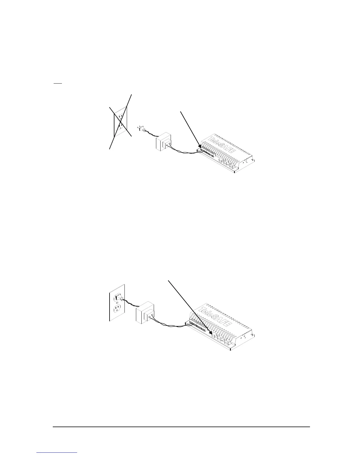
3.1 Connect Input Power
Connect the 16Vrms or 24V wiring to the AC/DC PWR IN terminals on the 5203/5204 board. Do
not apply power to the controller at this time.
3.2 Power Up In Cold Boot Mode
This procedure initializes the serial communication parameters and the I/O database registers to
their default values, erases the Register Assignment, Ladder Logic and C programs, and unlocks
the controller.
Hold down the LED POWER button.
Apply power to the Micro 16 controller.
Continue holding the LED POWER button for 25 seconds until the STAT LED begins to flash
on and off continuously.
Release the LED POWER button.
3.3 Connect Computer to TeleSAFE Micro 16
Connect a null modem cable from the computer serial port to com2 on the TeleSAFE Micro 16
controller board.