Connection Modbus RTU Module
5 Connection
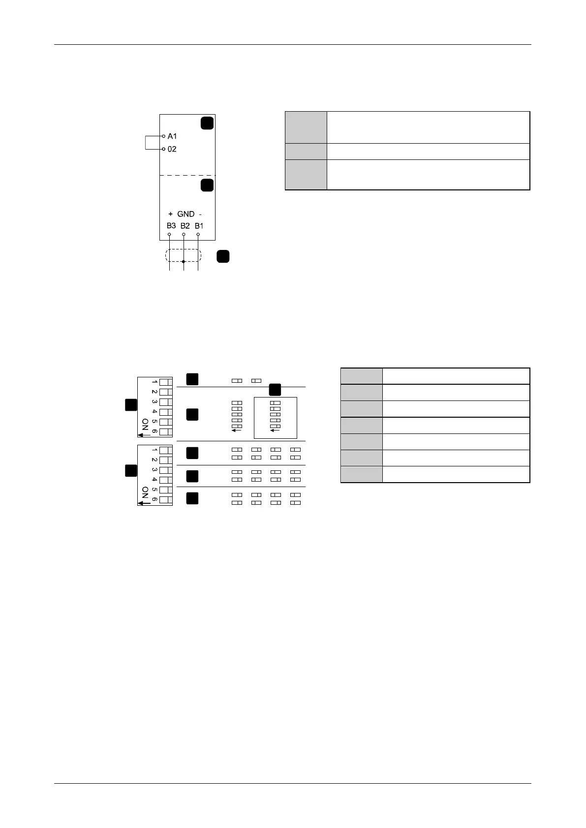
For the soft starter to accept fieldbus commands, a link must be fitted across terminals
A1-02 on the starter.
RS-485 connection onto Modbus
network
6 Device Configuration
6.1 Adjustment
Network communication parameters must be set on the Modbus Module. DIP switch
settings take effect on the power-up of the Modbus Module via the soft starter.
4800
9600
19200
38400
10 bit
10 s
60 s
100 s
AP
ASCII
RTU
+16
+8
+4
+2
+1
0
0
0
0
0
+16
+8
+4
+2
+1
0
0
0
0
0
03191.B
A
B
OFF
OFF
OFF
ON
ON ON
ONOFF
OFF
OFF ON
ON ON
ON
ON
ON ON
ON
OFF ON
OFF
OFF
OFF
OFF
OFF
OFF
No Parity ODD EVEN
No Time Out
ON ON
1
2
3
4
5
7
6
6
Baud rate
DIP switch
6.2 Master Configuration
For standard Modbus 11-bit transmission, the Master must be configured for 2 stop bits
with No Parity and 1 stop bit for odd or even parity.
For 10-bit transmission, the Master must be configured for 1 stop bit.
In all cases, the Master baud rate and slave address must match those set on the Modbus
Module DIP switches.
The data polling interval must be long enough for the module to respond. Short polling
intervals may cause inconsistent or incorrect behaviour, particularly when reading multiple
registers. The recommended minimum polling interval is 300 ms.
4