WebRelay-10 Plus™ Users Manual
Xytronix Research & Design, Inc. Page 10
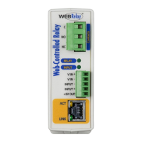
2.2 Connections
CAUTION: MAKE SURE POWER IS SHUT OFF BEFORE WIRING!
CAUTION: THIS UNIT SHOULD BE INSTALLED BY A QUALIFIED TECHNICIAN.
MIS-WIRING OR MIS CONFIGURATION COULD CAUSE PERMANENT DAMAGE TO THE WebRelay-10
Plus™ AND/OR THE EQUIPMENT TO WHICH IT IS CONNECTED.
Relay connections are made through the ¼ inch male tab connectors. Mating connectors (¼ inch female tab
connectors) can be purchased at electrical supply stores.
It is recommended that the load (device to be controlled) not be connected to WebRelay-10 Plus™ until after
WebRelay-10 Plus™ has been congured and tested. By doing this, wiring and conguration mistakes will not
cause the attached devices to turn on unexpectedly.
IMPORTANT: WIRES SHOULD BE PROPERLY CRIMPED TO THE CONNECTORS, AND CONNECTORS
SHOULD BE PROPERLY ATTACHED TO THE CIRUCIT BOARD OR RELAYS!
2.2.1 Power Supply Connection
WebRelay-10 Plus™ requires power for its internal logic circuits. Connect a 9-28VDC power supply to the
Vin+ and Gnd terminals. Note that a regulated power supply is recommended, such as a wall-mount AC-DC
adapter. Verify that the adapter is rated for the operating current of WebRelay-10 Plus™ (See Appendix H:
Specications for current requirements.)
Multiple WebRelay-10 Plus™ units may be connected to a single power supply by connecting the power supply
input terminals in parallel. The power supply must have a high enough current rating to power all units connected.
(See Appendix H: Specications for current requirements.)
The power input tab terminals are 1/4” x .032”. Use UL listed quick-connect connectors suitable for eld
connections. Use a suitable crimping tool as specied by the connector manufacturer. Use wire rated for 75ºC
(min) for the power connections.
2.2.2 Relay Connection
Direct connection to relay contacts is provided through tab connectors located on the top of the relays. Do not
exceed the specied load ratings for relay contacts (see Appendix H: Specications for load ratings). The
relay tab terminals are 1/4” x .032”. Use UL listed quick-connect connectors suitable for eld connections. Use a
suitable crimping tool as specied by the connector manufacturer. Use wire rated for 75ºC (min) for connections to
the relays.
2.2.3 Network Connection
Connect the Ethernet port to a 10 Base-T or 10/100 Base-T Ethernet connection. This typically connects to an
Ethernet hub, switch, or router. For conguration, WebRelay-10 Plus™ may be connected directly to the Ethernet
port on a computer using a “crossover” cable. Otherwise, for connection through a hub or router, a standard
“straight-through” cable should be used.