MiniWarden Manual • 530-205-4520 • 10
Sensor Wire Connections
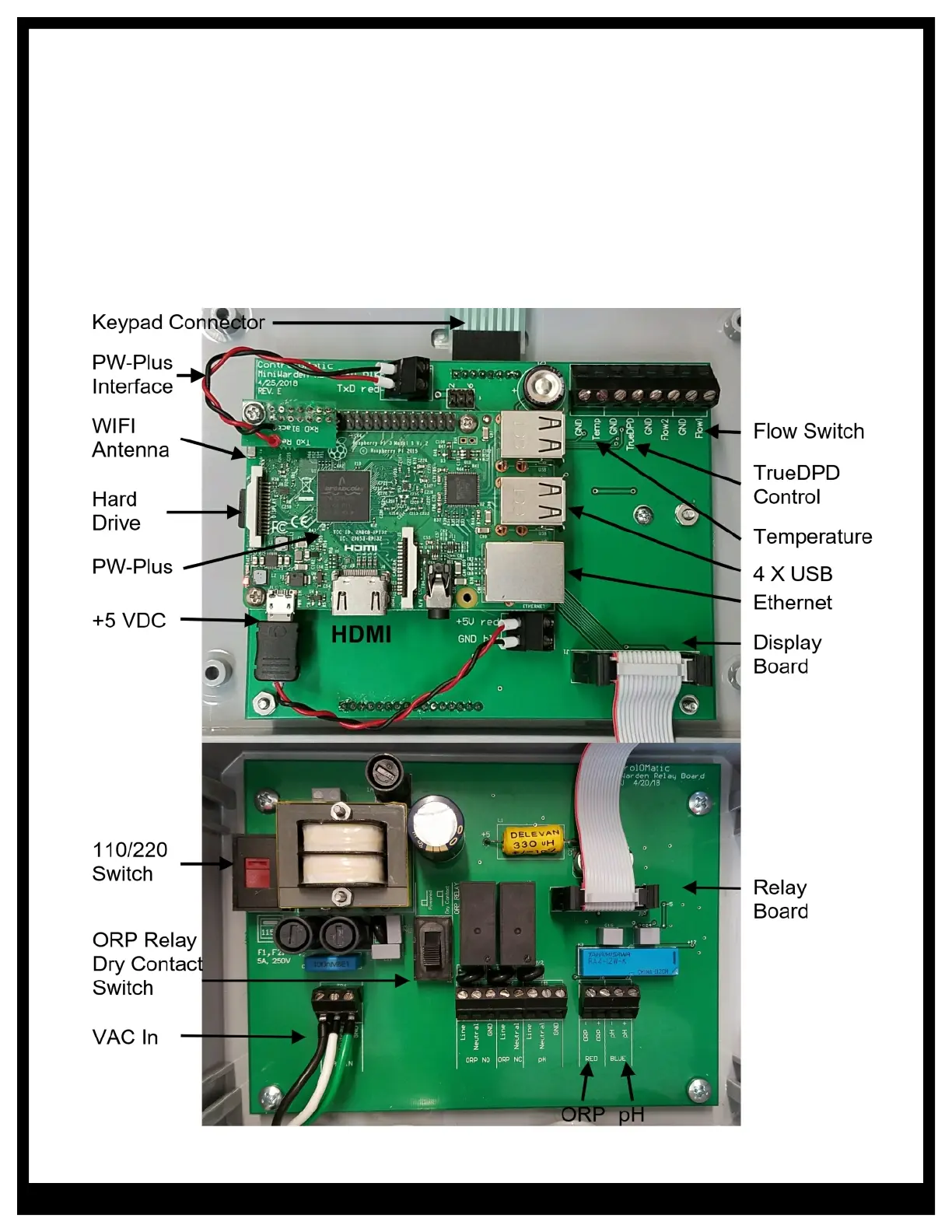
If not pre-mounted, route the pH (Blue Sensor Wire), ORP (Red Sensor Wire), gray flow switch and the
gray temperature sensor wire through the small cable grip on the right side on the bottom part of the
controller and connect as labeled inside MiniWarden or as indicated below in PICTURE 3. Please Note:
Black wires are always negative (-) and the Clear or Red wires are always positive (+).
● Flow Sensor Connection: Connect flow the sensor to Flow1 on the display board on the lid.
● Temperature Sensor Connection: Connect the sensor to the Temp connection on the display board
on the lid.
● ORP and pH Sensors: Connect to the appropriate connector on the Relay Board.