3PROPELLER WALL IO&M B51091-003
2 Speed, 1 Winding, 3-Phase Motor
Motor
1
2
3
4
5
6
Together
Line
L
1
L
2
L
1
2
3
4
5
6
Open
L
1
L
2
L
3
Motor
To reverse, interchange any two line leads. Motors require
magnetic control.
2 Speed, 2 Winding, 3-Phase
L
1
T
1
T
2
T
3
Low Speed
Low Speed
Low Speed
High Speed
High Speed
High Speed
Motor
T
13
T
12
T
11
L
2
Line
L
3
To reverse: High Speed: interchange leads T
11
and T
12
; Low
Speed: interchange leads T
1
and T
2
; Both Speeds: interchange
any two line leads.
Typical Damper Motor Schematic
Fan
Motor
Damper
Motor*
Second
Damper
ansformer**
Transformer*
L3
L2
L1
For 3-Phase, damper motor voltage should be the same be-
tween L
1
and L
2
. For single phase application, disregard L
3
.
*Damper motors may be available in 115, 230 and 460 volt
models. The damper motor nameplate voltage should be veried
prior to connection.
**A transformer may be provided in some installations to cor-
rect the damper motor voltage to the specied voltage.
Shutters
If your fan is supplied with a shutter, follow the direction
below. If your fan is not supplied with a shutter, proceed to
Final Installation Steps.
To ensure long-life, make a weather-proof seal by using
a good quality silicon caulking under the shutter ange.
1. Place the shutter into the wall opening.
2. Mount the shutter to the supporting surface using
Number 12 sheet metal screws on six inch centers
around the perimeter.
3. Manually operate the shutter to ensure the blades
move freely.
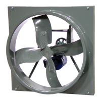
Wall Fans with Wall Housing
1. Remove end guard from the wall housing.
2. Drill a hole through either side panel at a convenient
location and pull the wires through. Do not pull wires
through wire guard at the back panel.
3. Restrain the incoming wire at the side panel to pre-
vent excess wire from entering the shaft and propel-
ler area.
Wiring Diagrams
Single Speed, Single Phase Motor
T-1
4
L
2
L
1
When ground is required, attach to ground A or B with No. 6
thread forming screw. To reverse, interchange T-1 and T-4.
2 Speed, 2 Winding, Single Phase Motor
T-1
4
Low Speed
High Speed
L
1
L
2
When ground is required, attach to ground A or B with No. 6
thread forming screw. To reverse, interchange T-1 and T-4 leads.
Single Speed, Single Phase, Dual Voltage
J-10
T-5
Link A
Link B
Low Voltage
Line
L
2
L
1
Link A
and B
L
1
L
2
Line
T-5
J-10
When ground is required, attach to ground A or B with No. 6 thread
forming screw. To reverse, interchange T-5 and J-10 leads.
3-Phase, 9 Lead Motor
4
5
6
1
7
2
8
3
9
L
1
L
2
L
3
456
7
8
9
12
3
L
1
L
2
L
3
Low Voltage
208/230 Volts
High Voltage
460 Volts
3 Phase, 9 Lead Motor
Y-Connection
7
1
6
789
4
5
6
12
3
Low Voltage
olts
High V
460 Volts
8
2
4
9
3
5
L
L
L
L
1
L
3
L
2
3 Phase, 9 Lead Motor
Delta-Connection
To reverse, interchange any two line leads.