7PROPELLER WALL IO&M B51091-003
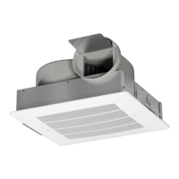
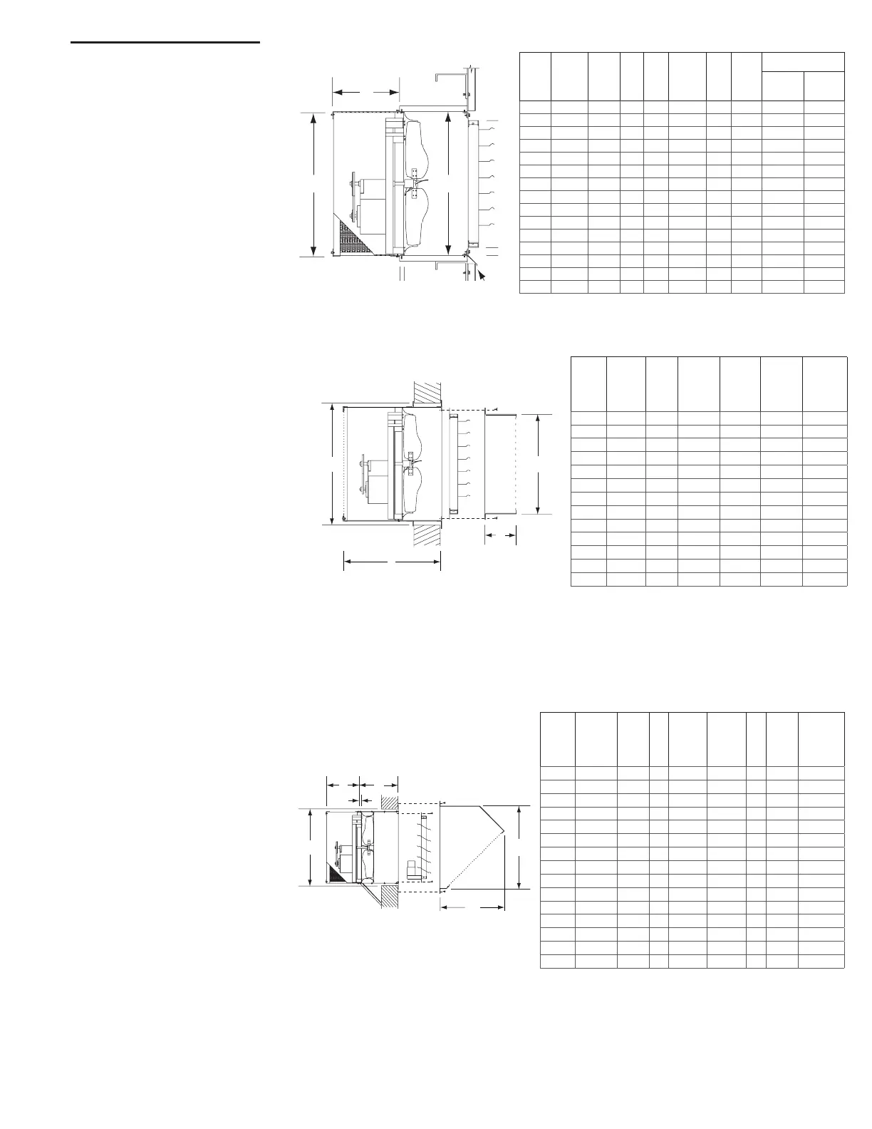
Exhaust Package Fan with
Shutter Guard
Illustrated is the typical installa-
tion of an exhaust PAC-Fan in a ma-
sonry wall with a shutter guard. The
installer provides suitable fasteners
(Hex bolts or Lag screws) to support
the fan. It is recommended that 5/16”
minimum bolts on 6” to 10” centers be
used on the perimeter of the housing.
Mounting ange should be caulked to
exterior of the wall. Fans with motors
in excess of 80 lbs. should be addi-
tionally supported by hanging rods or
supports placed underneath the fan.
A
7
WO
B
APB,
APD,
SPD
XLP,
XLPH,
XMP,
XMPH
EPB,
EPD
A
B-
Direct
B-Belt WO
8 - - 10-5/8 13-5/8 - 13-1/4
10-12 - - 14-5/8 17-5/8 - 17-1/4
14-16 - - 18-5/8 20 - 21-1/4
18-20 20 - 22-5/8 22 34-1/4 25-1/4
24 24 - 27-7/8 23 34-1/4 31-1/4
30 30 24 33-7/8 24-3/8 37-7/8 37-1/4
36 36 30 39-7/8 28-3/8 39-3/8 43-1/4
42 42 36 45-7/8 33-5/8 40-5/8 49-1/4
48 48 42 51-7/8 39-5/8 50-5/8 55-5/16
- 54 48 57-7/8 40-1/8 47-3/4 61-5/16
- 60 54 63-7/8 44-3/4 47-3/4 67-1/2
- - 60 69-7/8 - 47-3/4 73-1/2
- - 72 81-7/8 - 50-3/4 85-1/2
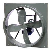
Exhaust Fan with Osha
Wire Guard & Shutter
Illustrated is the typical installa-
tion of an exhaust wall fan with an
OSHA wire guard and shutter in
a steel structure with corrugated
siding. The installer will provide
a sleeve of suitable material to
support the fan at a correct dis-
tance from the shutter (minimum
distance is the “A” dimension).
WO
C
B
Fan support and flashing by others.
AWB
AWD
SWD
XLW
XLWH
XMW
XMWH
EWB
EWD
A B C D E
WO
Std.
Fan
Wire
Guard.
8 - - 11 13 12-3/4 10 1 12-1/2 13-1/4
10-12 - - 12 13 16-3/4 14 1 16-7/16 17-1/4
14-16 - - 12 13 20-3/4 18 1 20-7/16 21-1/4
18-20 - - 13 12 24-3/4 22 1 24-7/16 25-1/4
- 20 - 13 21 24-3/4 22 1 24-7/16 25-1/4
24 - - 15 21 30-3/4 27 1-1/2 30-7/16 31-1/4
- 24 - 15 13 30-3/4 27 1-1/2 30-7/16 31-1/4
30 30 24 16 21 36-3/4 33 1-1/2 36-7/16 37-1/4
36 36 30 16 21 42-3/4 39 1-1/2 42-7/16 43-1/4
42 42 36 17 26 48-7/8 45 1-1/2 48-7/16 49-1/4
48 48 42 17 26 54-7/8 51 1-1/2 54-7/16 55-5/16
- 54 48 17 28 60-7/8 57 1-1/2 60-7/16 61-5/16
- 60 54 17 28 66-7/8 63 1-1/2 66-7/16 67-1/2
- - 60 17 28 72-7/8 69 1-1/2 72-7/16 73-1/2
- - 72 17 31 84-7/8 81 1-1/2 84-7/16 85-1/2
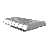
Supply Fan with Wall
Collar, Osha Wire Guard,
Motorized Supply Shutter
& Weather Hood
Illustrated is the typical installa-
tion of a supply wall fan in a ma-
sonry wall with a wall collar, OSHA
wire guard, motorized supply shut-
ter and weather hood. The installer
provides suitable fasteners to sup-
port the fan. Fasteners should be
placed on 6” to 10 centers on the
perimeter of the wall collar. Wall
collar should be caulked to the
exterior of the wall. The weather
hood should be securely fastened
and sealed to the wall. Fans with
motors in excess of 80 lbs. should
be additionally supported by hang-
ing rods or supports placed under-
neath the fan.
WO
A
DC
E
Hood Free Area
AWB
AWD
SWD
XLW
XLWH
XMW
XMWH
EWB
EWD
A B C D E WO
8 - - 18 16 12 13 1 13-1/4
10-12 - - 22 18-3/4 14-3/8 13 1 17-1/4
14-16 - - 26 21-3/4 15-3/8 13 1 21-1/4
18-20 - - 30 24-1/2 17-5/8 13 1 25-1/4
- 20 - 30 24-1/2 17-5/8 21 1 25-1/4
24 - - 30 24-1/2 17-5/8 13 1-1/2 31-1/4
- 24 - 34 27-1/4 18-3/4 21 1-1/2 31-1/4
30 30 24 40 31-1/2 18-3/4 21 1-1/2 37-1/4
36 36 30 46 35-3/4 19-1/2 21 1-1/2 43-1/4
42 42 36 52 40 19-1/2 26 1-1/2 49-1/4
48 48 42 58 44-1/4 19-3/4 26 1-1/2 55-5/16
- 54 48 64 48-1/2 19-3/4 28 1-1/2 61-5/16
- 60 54 70 52-3/4 19-3/4 28 1-1/2 67-1/2
- - 60 76 57 19-3/4 28 1-1/2 73-1/2
- - 72 88 67-1/2 19-3/4 31 1-1/2 85-1/2
Typical Installations
(Dimensions are in inches)
 Loading...