5PROPELLER WALL IO&M B51091-003
Changing Shaft Speed
All belt driven Propeller Wall fans with motors up to and
including 5HP are equipped with variable pitch pulleys. To
change the fan speed, perform the following:
1. Loosen setscrew on driver (motor) pulley and remove
key, if equipped.
2. Turn the pulley rim to open or close the groove facing.
If the pulley has multiple grooves, all must be adjusted
to the same width.
3. After adjustment, inspect for proper belt tension.
Speed Reduction
Open the pulley in order that the belt rides deeper in the
groove (smaller pitch diameter).
Speed Increase
Close the pulley in order that the belt rides higher in the
groove (larger pitch diameter). Ensure that the RPM lim-
its of the fan and the horsepower limits of the motor are
maintained.
Maximum RPM
EWB
Size
Maximum
RPM
AWB
Size
Maximum
RPM
APB
Size
Maximum
RPM
24 1675 24 1510 24 1005
30 1370 30 1145 30 800
36 1310 36 990 36 645
42 1175 42 905 42 660
48 1215 48 900 48 605
54 960 - - - -
60 890 - - - -
72 700 - - - -
XLP/XLPS
Size
Maximum RPM
XLPH/XLPHS
Size
Maximum RPM
20 1280 - -
24 1012 24 1100
30 666 30 1074
36 566 36 895
42 424 42 870
48 356 48 761
54 316 54 472
60 260 60 446
XMP/XMPS
Size
Maximum RPM
XMPH/XMPHS
Size
Maximum RPM
20 1280 - -
24 1276 24 1385
30 830 30 1175
36 680 36 948
42 498 42 829
48 414 48 726
54 346 54 522
60 318 60 530
XLW/XLWS
Size
Maximum RPM
XLWH/XLWHS
Size
Maximum RPM
20 1276 - -
24 1018 24 1126
30 674 30 1074
36 570 36 895
42 422 42 870
48 356 48 761
54 320 54 478
60 256 60 438
XMW/XMWHS
Size
Maximum RPM
XMWH/XMWHS
Size
Maximum RPM
20 1462 - -
24 1272 24 1385
30 860 30 1175
36 672 36 948
42 498 42 829
48 416 48 726
54 350 54 522
60 320 60 530
In severe applications, high temperatures or excessive
contaminates, it is advisable to have the maintenance de-
partment disassemble and lubricate the bearings after 3
years of operation to prevent interruption of service.
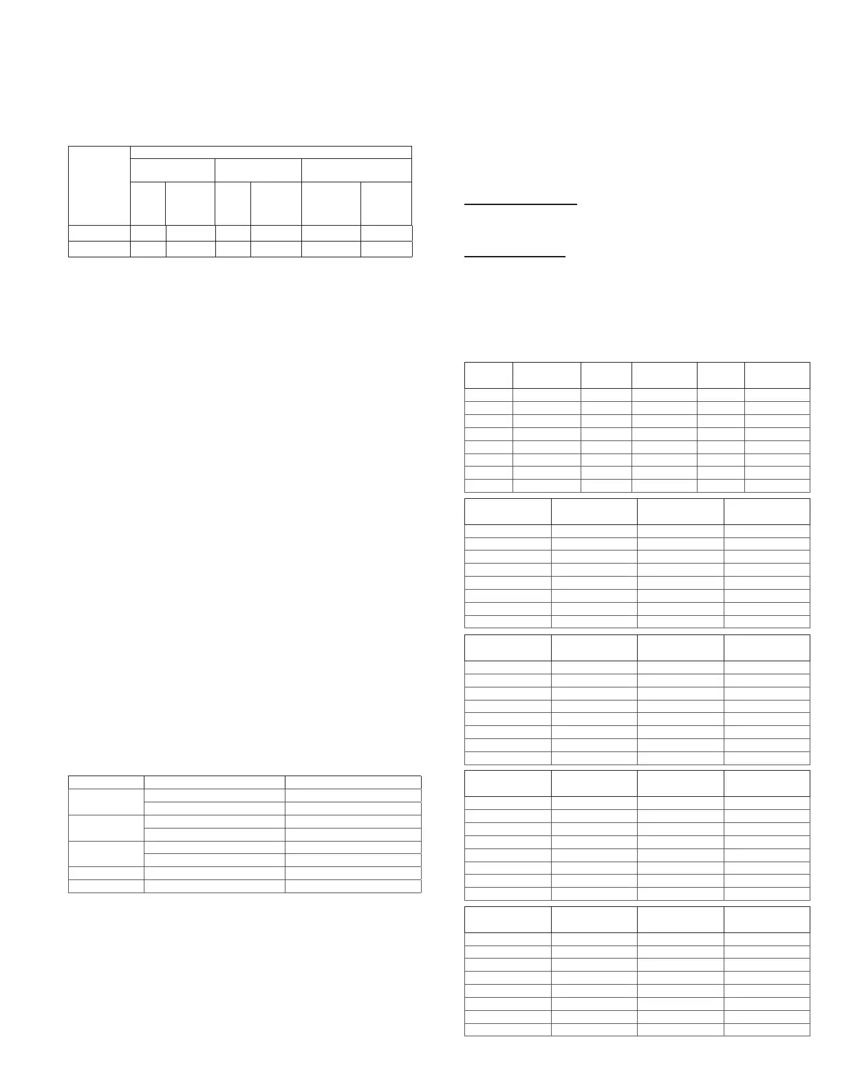
For motors with provisions for relubrication, follow inter-
vals of the table below.
Relubrication Intervals
Service
Conditions
Nema Frame Size
Up to and
Including 184T
213T-365T 404T and Larger
1800
RPM
and
Less
Over
1800
RPM
1800
RPM
and
Less
Over
1800
RPM
1800 RPM
and Less
Over
1800
RPM
Standard 3 yrs. 6 months 2 yrs. 6 months 1 yr. 3 months
Severe 1 yr. 3 months 1 yr. 3 months 6 months 1 month
Motors are provided with a polyurea mineral oil NGLI #2
grease. All additions to the motor bearings are to be with
a compatible grease such as Exxon Mobil Polyrex EM and
Chevron SRI.
The above intervals should be reduced to half for vertical
shaft installations.
Fan Bearings
The fan bearings are provided prelubricated. Any spe-
cialized lubrication instructions on fan labels supersedes
information provided herein. Bearing grease is a petro-
leum lubricant in a lithium base conforming to an NLGI #2
consistency. If user desires to utilize another type of lu-
bricant, they take responsibility for ushing bearings and
lines, and maintaining a lubricant that is compatible with
the installation.
An NLGI #2 grease is a light viscosity, low-torque, rust-
inhibiting lubricant that is water resistant. Its temperature
range is from -30°F to 200°F and capable of intermittent
highs of 250°F.
Bearings should be relubricated in accordance with the
condition chart below.
For best results, lubricate the bearing while the fan is in
operation. Pump grease in slowly until a slight bead forms
around the bearing seals. Excessive grease can damage
seal and reduce life through excess contamination and/or
loss of lubricant.
In the event that the bearing cannot be seen, use no
more than three injections with a hand operated grease
gun.
Conditions Chart
RPM Temp °F Greasing Interval
Up to 1000
-30 to 120 6 months
120 to 200 2 months
1000 to 3000
-30 to 120 3 months
120 to 200 1 month
Over 3000
-30 to 120 1 month
120 to 200 2 weeks
Any Speed < -30 Consult Factory
Any Speed > 200 1 week
For moist or otherwise contaminated installations; divide the in-
terval by a factor of three. For vertical shaft installations divide the
interval by a factor of two.
Motor Services
Should the motor prove defective within a one-year pe-
riod, contact your local Loren Cook representative or your
nearest authorized electric motor service representative.
 Loading...