16
Technical Information
Service Manual
5. Electrical Part
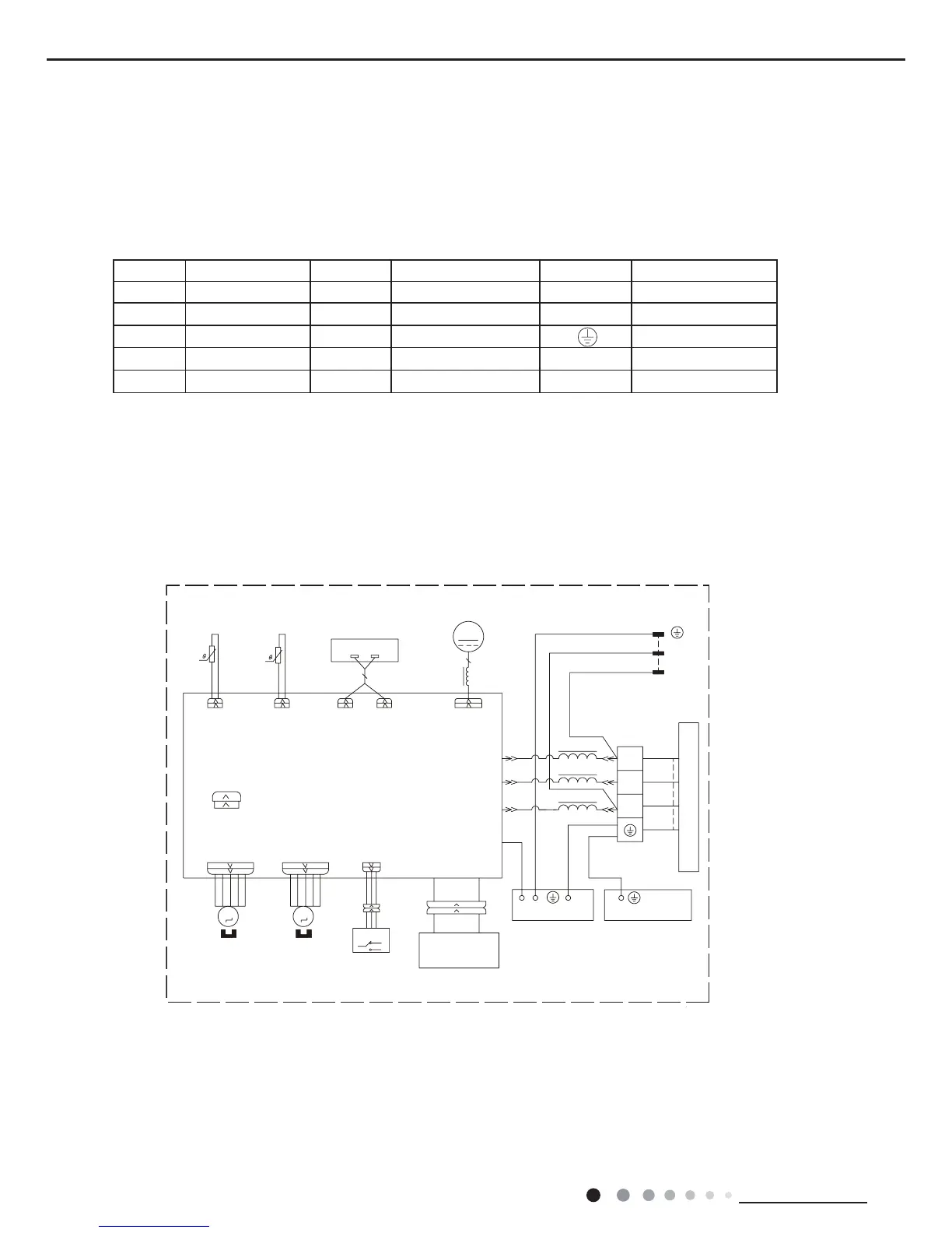
5.1 Wiring Diagram
● Indoor Unit
● Instruction
Symbol Symbol Color Symbol Symbol Color Symbol Name
WH White GN Green CAP Jumper cap
YE Yellow BN Brown COMP Compressor
RD Red BU Blue Grounding wire
YEGN Yellow/Green BK Black / /
VT Violet OG Orange / /
Note: Jumper cap is used to determine fan speed and the swing angle of horizontal lover for this model.
/
/
6:,7&+
<(*1
%.
%8
0
6:,1*'2:1
287'22581,7
&$3
-803
$335,17('&,5&8,7%2$5'
5220
57
57
78%(
6(1625 6(1625
52207(03
78%(7(03
32:(5
%8:+
/
1
1
',63/$<
5(&(,9(5$1'
',63/$<%2$5'
',63
$3
',63
0
)$1
'&02725
02725
67(33,1*
6:,1*83
0
$3
6
&1
6(/(&7
02725
67(33,1*
02725
%1%.
<(*1*1
1
;7
%1
&20287
$&/
%8
%.
%1
3(
(9$325$725
<(*1
7(50,1$/
%/2&.
/
(
(/(&75,&%2;
3(
<(*1
<(*1
/
0$*1(7,&
5,1*
&2/'3/$60$
*(1(5$725
+($/7+1
+($/7+/
; ;
5' %8
5' %8