496371 Issue 1 17 of 20
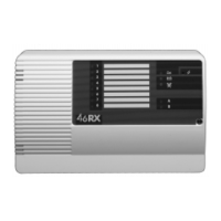
1. Set Mode Switches 4 to 8 as follows:
on
1 2 3 4 5 6 7 8
2. Activate a transmitter
Channel 1 and the jamming LED flash for the duration of the transmis-
sion.
The LEDs stop flashing, leaving one channel LED glowing steadily.
3. Repeat step 2 several times (four or five) until you obtain consistent
results.
The number of the channel LED that glows steadily at the end of each test
shows the quality of the signal. Channel 1 LED (or no LED lit) indicates a very
poor signal. Channel 8 LED indicates a very good signal.
If any transmitter gives a reading of 3 or less then the quality is not good
enough for reliable reception.
Notes:
1) Ignore any indications on Common Outputs A and B during the test.
2) The unit flashes the Jamming LED on its own if it detects transmis-
sions from a device using an incorrect site code.
FAULT FINDING
The next page shows fault indications on the control panel. In the diagram
means a LED glows steadily, while means a LED flashes. The subse-
quent page shows other fault indications.
4618 Fault Finding