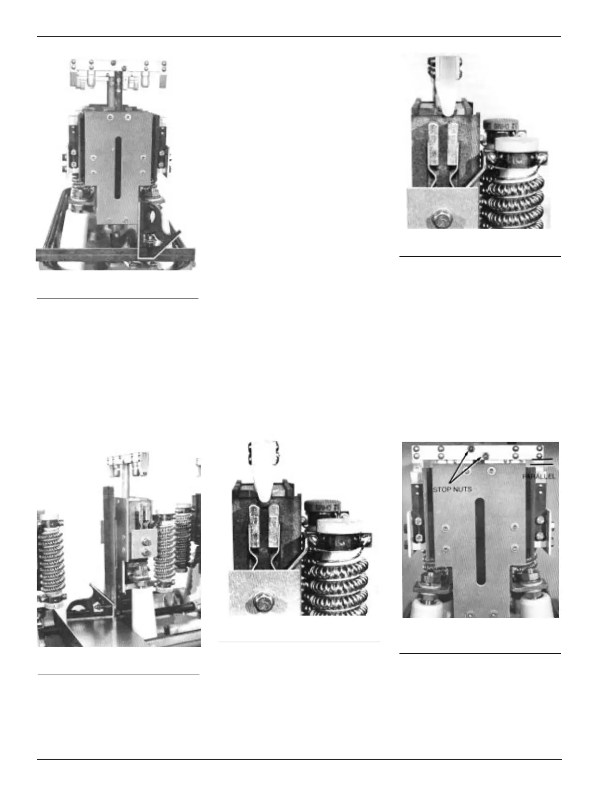
Figure 20.
Lateral vertical alignment.
Figure 21.
Longitudinal vertical alignment.
Figure 22.
Contacts aligned.
Figure 23.
Contacts misaligned.
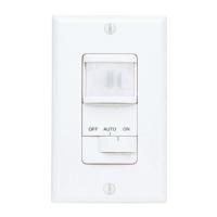
Figure 24.
Moving contact bar must be paral-
lel to end of contact housing.
10
B. With the contact housing squared,
tighten both outer hex nuts with-
out disturbing the position of the
inner nuts.
C. Using a flat plate spanning the
head casting as a base, square
the side of the contact housing
as shown in Figure 21. If not
square the contact housing can
be forced into the squared posi-
tion.
G. Viewing the contact assembly
from the end of the switch, as in
Figure 24, check that the mov-
ing contacts are entering
squarely into the moving con-
tacts. A visual check that the
moving contact bar is parallel to
the edge of the housing is ade-
quate assurance of this adjust-
ment.
If adjustment is needed,
loosen the two stop nuts slightly
and shift the moving contact
bar. Tighten stop nuts securely.
D. Unhook the closing spring from
the drive stud on the front of the
actuator mechanism. Install the
manual closing crank and crank
clockwise untiI the drive stud
reaches 7 o’clock position;
approximately 42 revolutions.
E. Crank slowly from this point, to
bring the moving contacts toward
the stationary contacts.
NOTE: If the switch is equipped with
the quick-close feature, the mecha-
nism will latch in the 7 o’clock posi-
tion. To release, push the plunger of
the quickclose solenoid up into the
solenoid.
F. As the moving arcing contacts
approach engagement with the
stationary contacts, observe their
alignment. See Figures 22 and
23. The moving contacts in Fig-
ure 22 will engage the stationary
contacts evenly, making simulta-
neous contact on both sides and
with equal contact force. The
moving contacts in Figure 23
might make entry into the sta-
tionary contacts but with unequal
contact force.
Contact misalignment can be
corrected by twisting the moving
contact assembly about its shaft.
The link at the end of the contact
rod will permit enough twist to
obtain the required adjustment.