2
INTRODUCTlON
Service Information S260-20-9 covers
the maintenance instructions for Types
VR VCR, and VLR motor operated oil
switches. This includes their general
description, operating principles and
instructions for periodic inspection, test-
ing, trouble shooting and shop repairs.
A service parts list, keyed to exploded
view drawings of the equipment is
included at the back of the manual.
NOTE: Maintenance instructions for early
(pre1970) versions of these switches is cov-
ered in the original service bulletin 287-
10SB-1.
GENERAL DESCRIPTlON
These oil-filled, electrically-operated
devices provide, three-phase switching
for general purpose loads (Type VR)
capacitive loads (Type VCR) and induc-
tive loads (Type VLR) on manual or
automatic command. These switches
utilize a common operating mechanism
and package configuration, and are dif-
ferentiated by their contact assemblies.
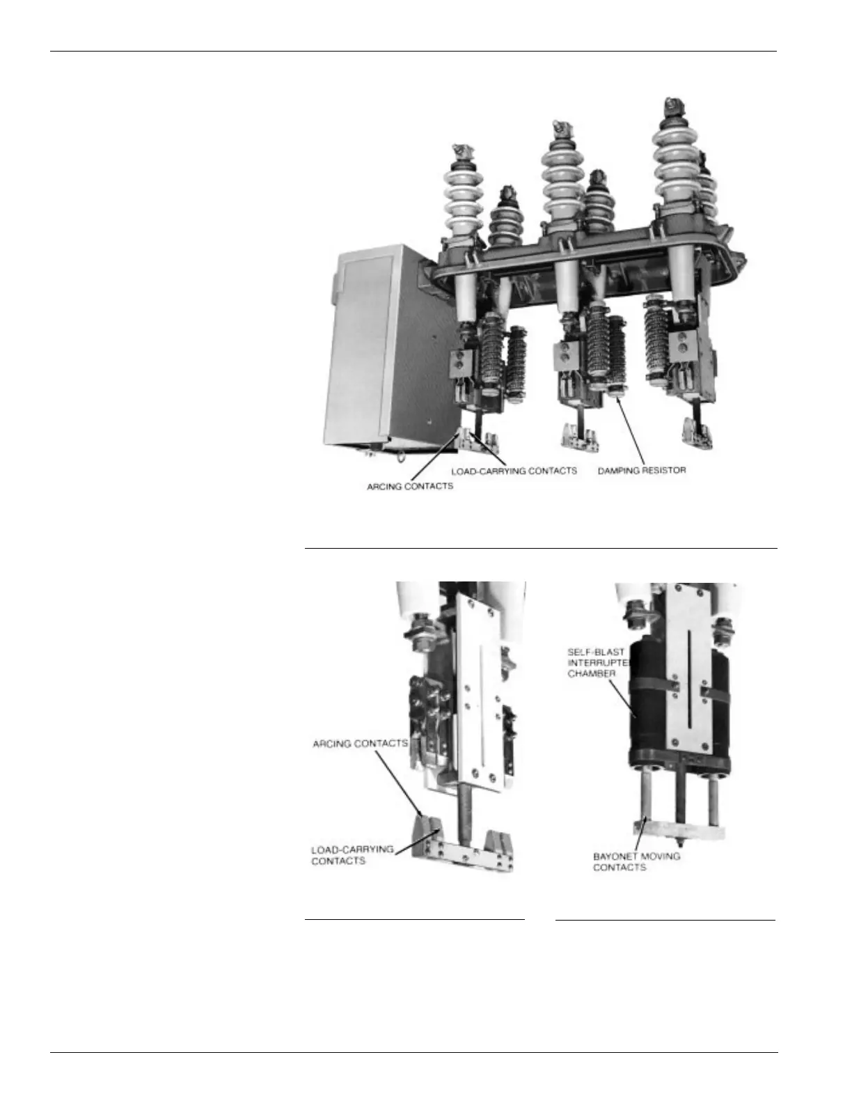
The Type VCR switch utilizes a set of
wedge-shaped moving contacts for arc-
ing and a set of bayonet-type contacts
for load-carrying. In addition, resistors in
series with the arcing contacts damp
both the magnitude and frequency of
transient inrush currents for parallel
capacitor bank switching applications
(Figure 2).
The Type VR switch utilizes two sets
of wedge-shaped moving contacts, one
set for arcing and the second for load-
carrying (Figure 3).
The Type VLR switch utilizes a set of
bayonet-type moving contacts which
operate within self-blast interrupter-
chambers for quick and effective arc
interruption when switching inductive
loads (Figure 4).
The contact structures for all three
phases are linked with bell cranks to a
common torque shaft operated by the
actuator mechanism located in the cabi-
net on the front of the switch.
Figure 2.
Untanked Type VCR switch.
Figure 3.
Type VR contact arrangement.
Figure 4.
Type VLR contact arrangement.