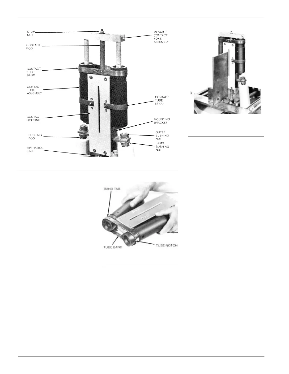
Figure 28.
Type VLR switch contact assembly.
Figure 29.
Dismantling contact tubes.
12
B. Lift the entire contact housing
assembly from the bushings and
the contact rod, which remains
attached to the operating link.
3. Disassemble the stationary contact
assembly.
A. Remove the contact tube straps
by removing the round head
machine screw and associated
hardware.
B. To free the contact tubes from the
housing, grasp a tube firmly in
each hand and with a slow
steady movement spread the
tubes away from the housing, as
shown in Figure 29, until the
band is released from the tubes.
C. Remove and discard the station-
ary contact tube assemblies.
4. Reassemble the stationary contact
structure with new contact tube
assemblies.
A. Use the reverse order of step 3B
and Figure 29 to reassemble the
tubes and tube band, making
sure the notch in the tube lines
up with the tab in the band.
B. Secure the tubes to the housing
with the tube straps.
5. Reinstall the stationary contact struc-
ture into the switch.
A. Install the assembly over the con-
tact rod and attach to the bush-
ing rods with the flat washers,
lockwashers, and brass nuts; do
not tighten.
Figure 30.
Checking axial and longitudinal
squareness with “sailboat” align-
ment fixture.
6. Align the stationary contact assembly.
A. With the switch mechanism in the
open position, the top of the dashpot
piston on the contact rod should be
1/32 inch above the top surface of
the dashpot. (See Figure 19.) Adjust
the nuts on the bushing rod to move
the contact housing up or down as
required.
B. With a “sailboat” alignment fixture
spanning the machined surfaces
of the head casting, check the
axial squareness of the contact
housing as shown in Figure 30.
obtain proper squareness by
adjusting the bushing nuts while
maintaining the alignment of step
6A.
NOTE: A typical sailboat alignment
fixture is shown in Figure 31. If a fix-
ture is not available the procedure for
aligning VR and VCR contact boxes,
described on page 31, can be used.
C. With the contact housing squared,
tighten both outer bushing nuts
securely without disturbing the
position of the inner nuts.
D. Square the side of the contact
housing with the head casting as
shown in Figure 30. If misalign-
ment exists, adjust by bending
the entire structure as required.
7. Install and align the movable contact
yoke assembly.
A. Replace the correct number of
washers above and below the
contact yoke as noted in Step 1
C during disassembly.
B. Reinstall roll pin, spacers, washer
and stop nut to complete the
reassembly.
C. Unhook the closing spring from
the drive stud and manually
crank the mechanism until the
drive stud reaches the 7 o’clock
position; approximately 42 revo-
lutions.
D. Crank slowly from this point to
bring moving contacts toward the
stationary contacts.
NOTE: If switch is equipped with
quickclose accessory, the mecha-
nism will latch in the 7 o-clock posi-
tion. To release, push the quick close
solenoid plunger up into the solenoid.
E. As the moving contacts approach
the stationary contacts observe
their alignment. Misalignment
can be corrected by twisting the
 Loading...


