WaveLinx Networked Relay Panel Quick Start (Version 15)
www.cooperlighting.com 2
Device Information
WaveLinx Area
Controller
• Communicates to the WaveLinx Mobile
App using onboard Wi-Fi or the building
LAN/WLAN
• Communicates via Ethernet to WaveLinx
Networked Relay Panels or optionally to
WaveLinx Area Hubs connected to
WaveLinx CAT devices
• Optionally communicates wirelessly (IEEE
802.15.4) to WaveLinx PRO devices
• Powered by a PoE Network Switch
WaveLinx
Networked
Relay Panel
• Available in a variety of enclosure sizes
• From 4 to 64 relay sizes
• Select Normal or Emergency models
• Powered from onboard transformer
• 120/277VAC option
• 120/347VAC option
• Relay options include 1, 2, or 3 pole
40 Amp relays
• Option to add 0-10V dimmer modules
• 1 module = four 0-10V dimmers
• Relay panel mount or remote mount
• Onboard display for basic relay control
and initial configuration
• Connects to Ethernet for communication
to the WaveLinx Area Controller.
• Responds to commands from the
WaveLinx Area Controller and WaveLinx
PRO and CAT devices
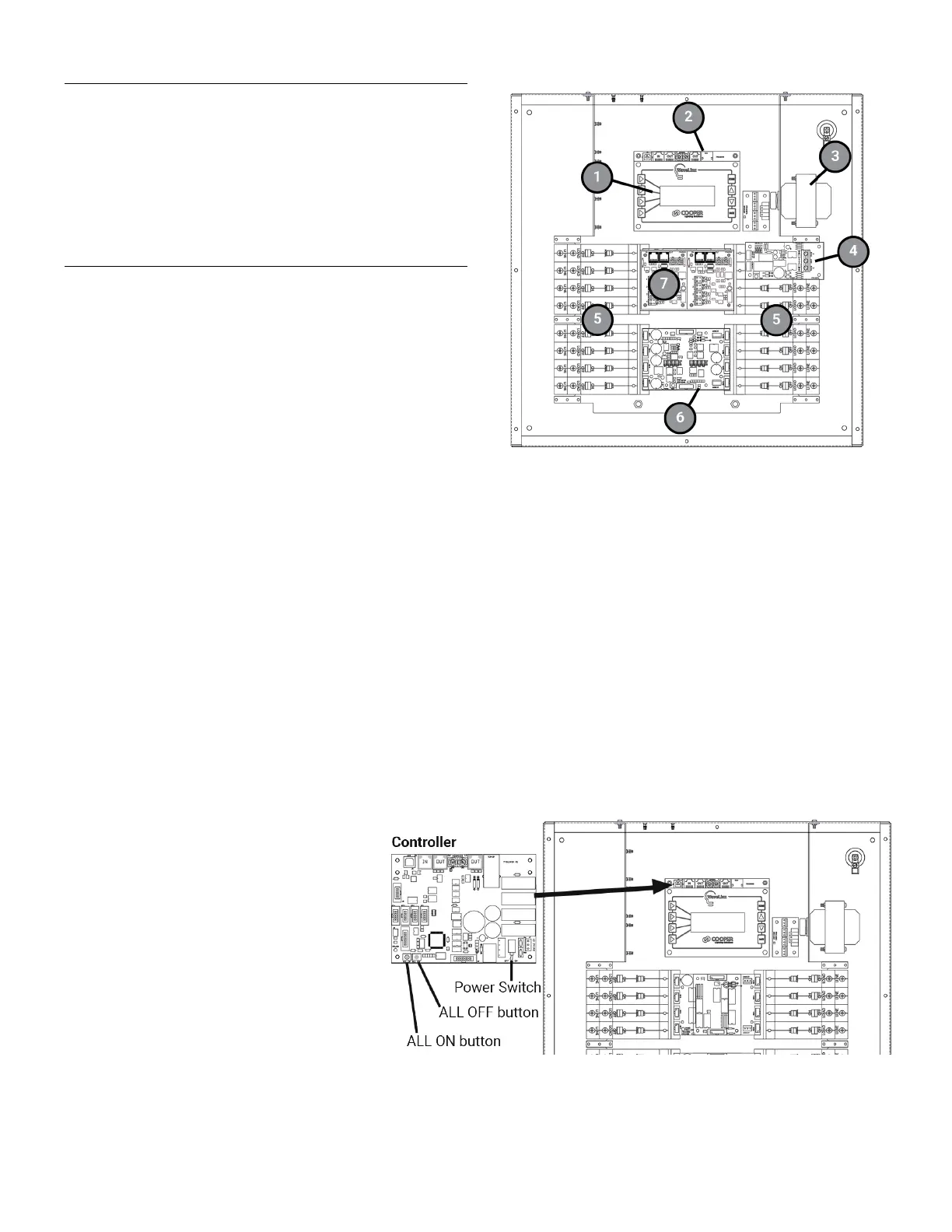
2: Controller Card
under display
3: Transformer
4: Phase Monitoring Module
(Emergency panels only)
5: Relays
6: Relay Output Module OR
Relay Bypass Module
(Emergency panels only)
under Dimming Module(s)
7: Dimming Module
Out of the Box
The WaveLinx Networked Relay Panel has no out-of-the box functionality.
Power Switch and Manual Relay Operation
Once power is applied, the relay override buttons and display allow manual operation of the relays and dimmers until a connection can
be made to the WaveLinx Area Controller.
relay panel’s Controller Card is under the
display and contains an ON/OFF power switch
.
switched off to the relay panel’s
without the need to switch the
Switch to the left to turn
OFF or to the right to turn power ON.
Relay ALL ON/ALL OFF Override Buttons
Controller Card also contains two onboard
buttons that allow manual control of all relays in the
panel. Press the left button to turn
all relays ON.
to turn all relays OFF. Relays
remain in that state until the next command.
 Loading...