6 Electrical Wiring & Connections
Warning - The following instructions involve working on a live electrical 230Vac system.
The following shall only be carried out by suitably qualified electrical persons that are
approved and certified to work on Coopers Fire Ltd. systems.
Ensure the Control Panel is fully isolated before proceeding.
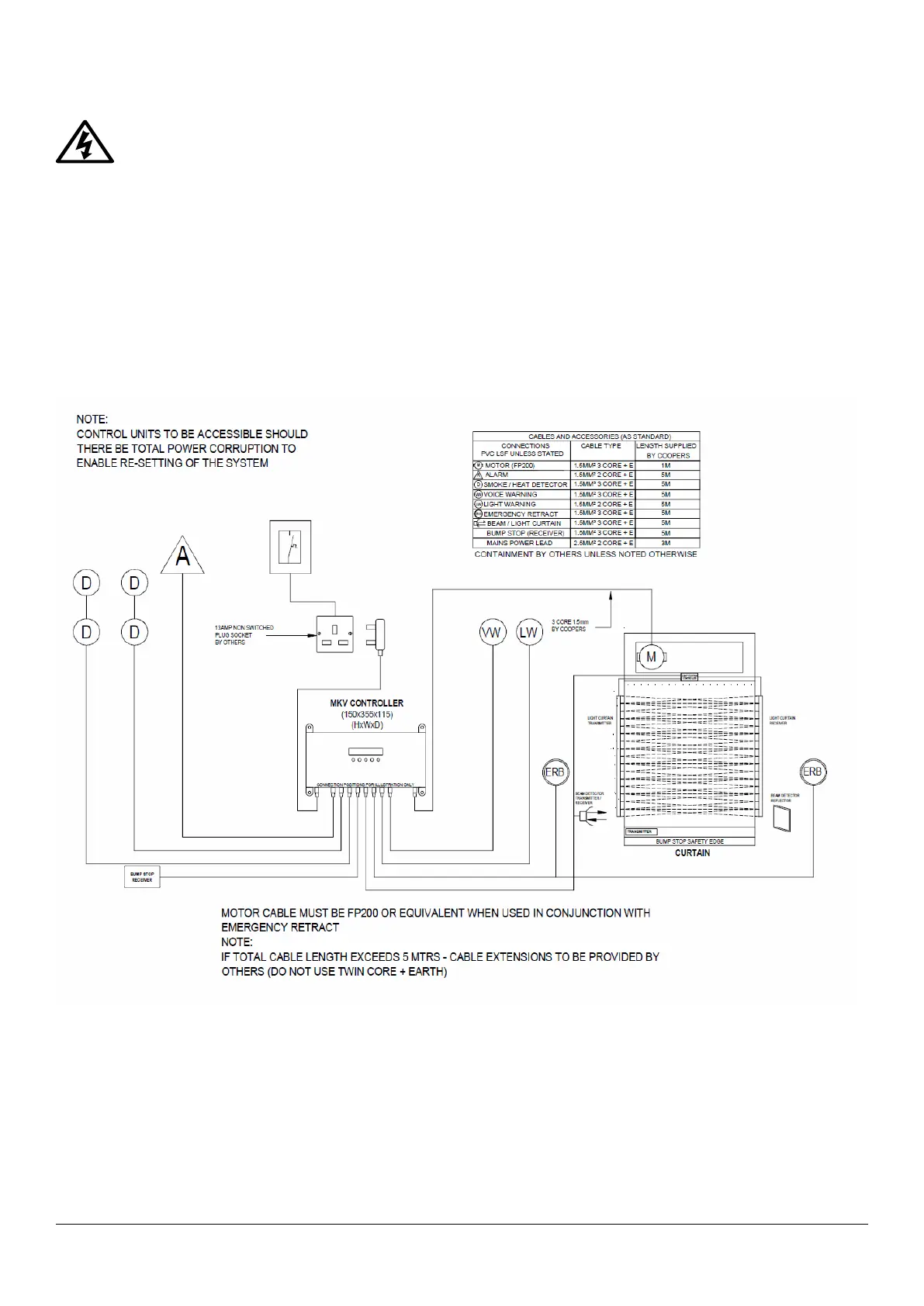
This manual is for general guidance. Attention must be paid to any site-specific requirements as
detailed in the Fitters Pack.
Any external circuits, including the connection to the Fire Alarm system, must be separated from
hazardous mains circuits by reinforced insulation.
6.1 Power Supply Unit (PSU)
Isolation from the mains supply is provided by both the plug and IEC inlet.
The mains outlet socket must be earthed.
A detachable power cord of inadequate rating must not be used.
 Loading...