3
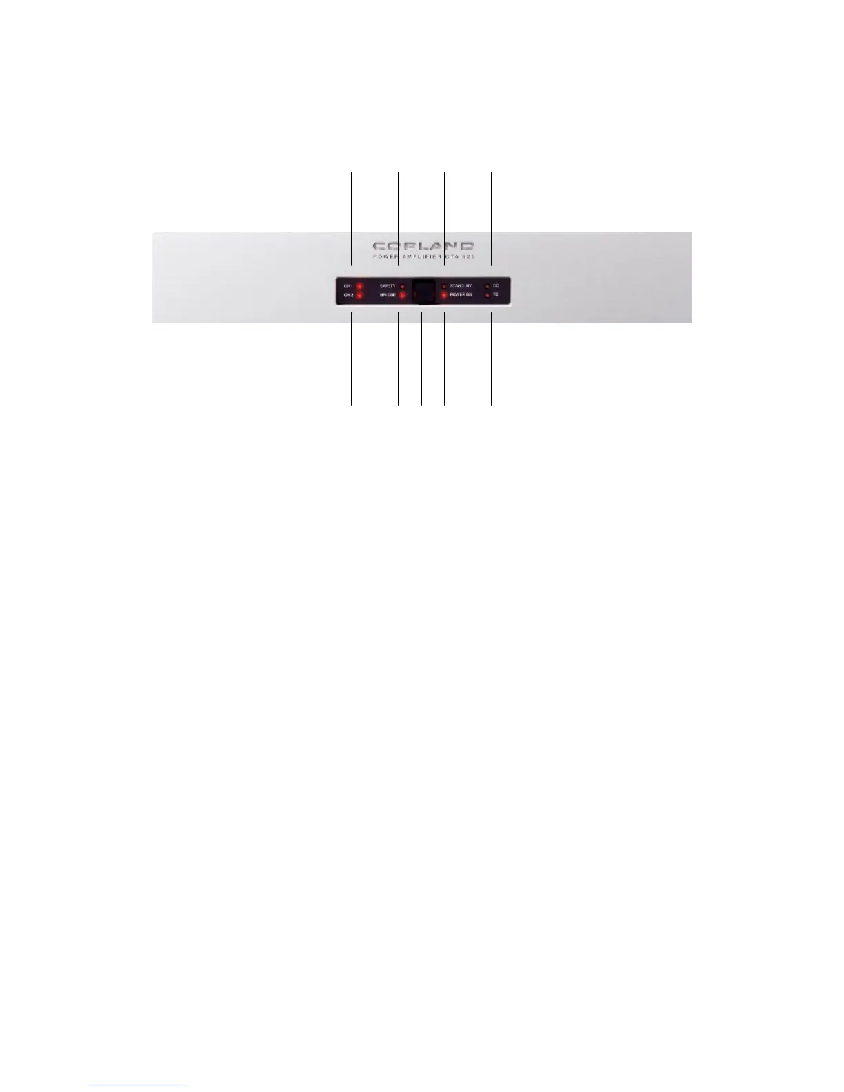
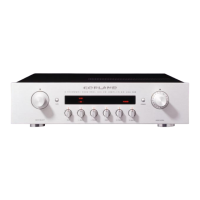
Front Panel
2 4 6 8
3 5 1 7 9
1 : On/St.By : By pressing this button, the amplifier will be switched between stand by
and operation mode cyclically.
2. CH1 : When amplifier are switched on this LED light indicate that Left channel are in
operation mode.
3. CH2 : When amplifier are switched on this LED light indicate that Right channel are in
operation mode.
4 : Safety : Indication for activation of protection circuitry.
5 : Bridge : Indication for bridge operation. LED will light when selector switch on the back
of the amplifier is placed in bridge position.
6 : Standby :
LED will light when amplifier is in stand by mode.
7 : Power on : LED will light when amplifier is on operation mode.
8 : DC : Indication for DC failure in amplifier. Protection circuitry will be activated.
9 : TE : Indication for temperature overload. Protection circuitry will be activated.