Copley Controls, 20 Dan Road, Canton, MA 02021, USA Tel: 781-828-8090 Fax: 781-828-6547
Tech Support: E-mail: sales@copleycontrols.com, Web: http://www.copleycontrols.com Page 2 of 32
RoHS
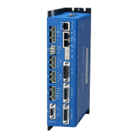
Xenus
PLUS
2-Axis
EtherCAT
800-1782
GENERALSPECIFICATIONS
Testconditions:Wyeconnectedload:2mHline-line.Ambienttemperature=25°C.Powerinput=230Vac,60Hz,1Ø
MODEL 800-1782
OUTPUTCURRENT(EACHAXIS)
PeakCurrent 20(14) Adc(Arms,sinusoidal)
Peak time 1 s
Continuouscurrent(Heatsinkrequired) 10(7) Adc(Arms,sinusoidal)
INPUTPOWER
Mainsvoltage,phase,frequency 100~240 Vac,±10%,1Øor3Ø,47~63Hz
MaximumMainsCurrent,1Ø(Note2,page3) 20 Arms
MaximumMainscurrent,3Ø(Note2,page3) 15.4 Arms
+24VdcControlpower +20to+32Vdc,0.5~1.1Adc(Note3,page3) Requiredforoperation
DIGITALCONTROL
DigitalControlLoops Current,velocity,position.100%digitalloopcontrol
Sampling rate(time) Currentloop:16kHz(62.5µs),Velocity&positionloops:4kHz(250µs)
Busvoltagecompensation Changesinbusormainsvoltagedonotaffectbandwidth
Minimum load inductance 200µHline-line
COMMANDINPUTS(NOTE:DIGITALINPUTFUNCTIONSAREPROGRAMMABLE)
Distributed Control Modes
CAN
application layer overEtherCAT(CoE) CyclicSynchronousPosition-Velocity-Torque,ProlePosition-Velocity-Torque,
InterpolatedPosition,Homing
Stand-alone mode
Analogtorque,velocity,positionreference ±10Vdc,14bitresolution Dedicateddifferentialanaloginput
Digitalpositionreference Pulse/Direction,CW/CCW Steppercommands(2MHzmaximumrate)
QuadA/BEncoder 2Mline/sec,8Mcount/sec(afterquadrature)
Digitaltorque&velocityreference PWM,Polarity
PWM=0%-100%,Polarity=1/0
PWM50% PWM=50%±50%,nopolarit
ysignalrequired
PWMfrequencyrange 1kHzminimum,100kHzmaximum
PWM minimum pulse width 220 ns
Indexing Upto32sequencescanbelaunchedfrominputsorASCIIcommands.
Camming Upto10CAMtablescanbestoredinashmemory
ASCII RS-232,DTE,9600~115,200Baud,3-wire,RJ-12connector
DIGITALINPUTS
Number 20
[IN1,11] Digital,Schmitttrigger,1µsRClter,24Vdccompatible,programmablepull-up/downto+5Vdc/ground,
Vt+=2.5~3.5Vdc,VT-=1.3~2.2Vdc,VH=0.7~1.5Vdc
[IN2~5,12~15] Programmableassingle-endedordifferentialpairs,100nsRClter,5Vdcmax,
10 kΩprogrammablepull-up/downperinputto+5Vdc/ground,
SE:Vin-LO≤2.3Vdc,Vin-HI≥2.7Vdc,VH=45mVtyp,DIFF:Vin-LO≤200mVdc,Vin-HI≥200mVdc,VH=45mVtyp,
[IN6~9] Opto-isolated,single-ended,±15~30Vdccompatible,bi-polar,groupof4withcommonreturn
Ratedimpulse≥800V,Vin-LO≤6.0Vdc,Vin-HI≥10.0Vdc,Inputcurrent±3.6mA@±24Vdc,typical
[IN16~19] DedicatedfunctionforNSKmotorlimitswitches.Internal6Vpowerwithcurrent-limitingresistors.
[IN10,20] Motorovertempsignalsonfeedbackconnectors,Schmitttrigger,
24Vdccompatible,
330µsRClter,4.99kpullupto+5Vdc,Vt+=2.5~3.5Vdc,VT-=1.3~2.2Vdc,VH=0.7~1.5Vdc
SAFETORQUEOFF(STO)INPUTS
Function PWMoutputsinactiveandcurrenttothemotorwillnotbepossiblewhentheSTOfunctionisactivated
Standard ConformancetoIEC61508-1,IEC61508-2,IEC61800-5-2,ISO13849-1
SafetyIntegrityLevel SIL3,Category3,PerformanceLeveld
Inputs 2two-terminal:STO_IN1+,STO_IN1-,STO_IN2+,STO_IN2-
Type Opto-isolators,24Vcompatible,Vin-LO≤6.0Vdcoropen,Vin-HI≥15.0Vdc,
Inputcurrent(typical) STO_IN1:11.2mA,STO_IN2:11.2mA
Responsetime 2ms(IN1,IN2)fromVin≤6.0Vdctointerruptionofenergysuppliedtomotor
Reference CompleteinformationandspecicationsareintheXenusPlusDual-AxisSTOManual
ANALOGINPUTS
Number 2
[AIN1~2] Differential,±10Vdc,5kΩ input impedance, 14-bit resolution
DIGITALOUTPUTS
Number 5
[OUT1~3] Opto-isolatedsolid-staterelays,60mAdcmax,24Vdctolerant,Ratedimpulse≥800V, series20ohmresistor
MOSFETchannelconnectsthe(±)outputs,Rds-On=10Ωmax@60mAdc,maxVout=32Vdc
Td-ON=5000µsmax@60mA,Td-OFF=5000µsmax@60mA,timesincluderise/falltimes
[OUT6~7] Motorbrakecontrol:opto-isolated,current-sinkingwithybackdiodeto
+24Vdc(J5-4~5),1Adcmax,Ratedimpulse≥800V
Td-ON=250µsmax@20mA,Td-OFF=250µsmax@200mA,timesincluderise/falltimes,
Programmable for other functions if not used for brake
RS-232PORT
Signals RxD,TxD,Gndin6-position,4-contactRJ-12stylemodularconnector,non-isolated,commontoSignalGround
Mode Full-duplex, DTE serial communication port for drive setup and control, 9,600 to 115,200 baud
Protocol BinaryandASCIIformats
ETHERCATPORTS
Format DualRJ-45receptacles,100BASE-TX
Protocol EtherCAT,CANapplicationlayeroverEtherCAT(CoE)
STATUSINDICATORS
AMP BicolorLED,drivestateindicatedbycolor,andblinkingornon-blinkingcondition
RUN GreenLED,statusofEtherCATstate-machine(ESM)
ERR RedLED,showserrorsduetotime-outs,unsolicitedstatechanges,orlocalerrors
L/A GreenLED,Link/Act,showsthestateofthephysicallinkandactivityonthelink(EtherCATconnection)
RUN,ERR,andL/ALEDcolorsandblinkcodesconformtoETG.1300S(R)V1.1.0
 Loading...