PIN SIGNAL PIN SIGNAL
1 FrameGnd 6 STO-IN1+
2 STO-IN1+ 7 STO-IN1-
3 STO-IN1- 8 STO-Bypass
4 STO-IN2+ 9 STO-Gnd
5 STO-IN2-
1
6
9
5
Frame Ground
STO-PWR (6.5 mA)
* XE2 and XEL-XPL STO bypass connections are different.
The diode shown should be used if XE2 and XEL-XPL drives are used on the same
equipment. Otherwise, the diode may be replaced by a jumper.
XE2 STO bypass connectors are not compatible with XEL-XPL drives.
*
STO-GND (Sgnd)
J6
Xenus Plus Dual-Axis
Bypass Plug Connections
Jumper pins:
2-4, 3-5, 6-8, 7-9 *
STO-1(+)
STO-2(+)
STO-2(-)
STO-1(-)
STO-1(+)
STO-1(-)
2
3
1
4
5
6
7
8
9
Upper IGBT Gate Drive
PWM Signals
Buffer
Voltage
Regulator
EN
+HV
PWM
Outputs
+VI
+VI
V_in
+VI
Lower IGBT Gate Drive
1
6
9
5
SAFETY
Copley Controls, 20 Dan Road, Canton, MA 02021, USA Tel: 781-828-8090 Fax: 781-828-6547
Tech Support: E-mail: sales@copleycontrols.com, Web: http://www.copleycontrols.com Page 7 of 32
RoHS
Xenus
PLUS
2-Axis
EtherCAT
800-1782
DESCRIPTION
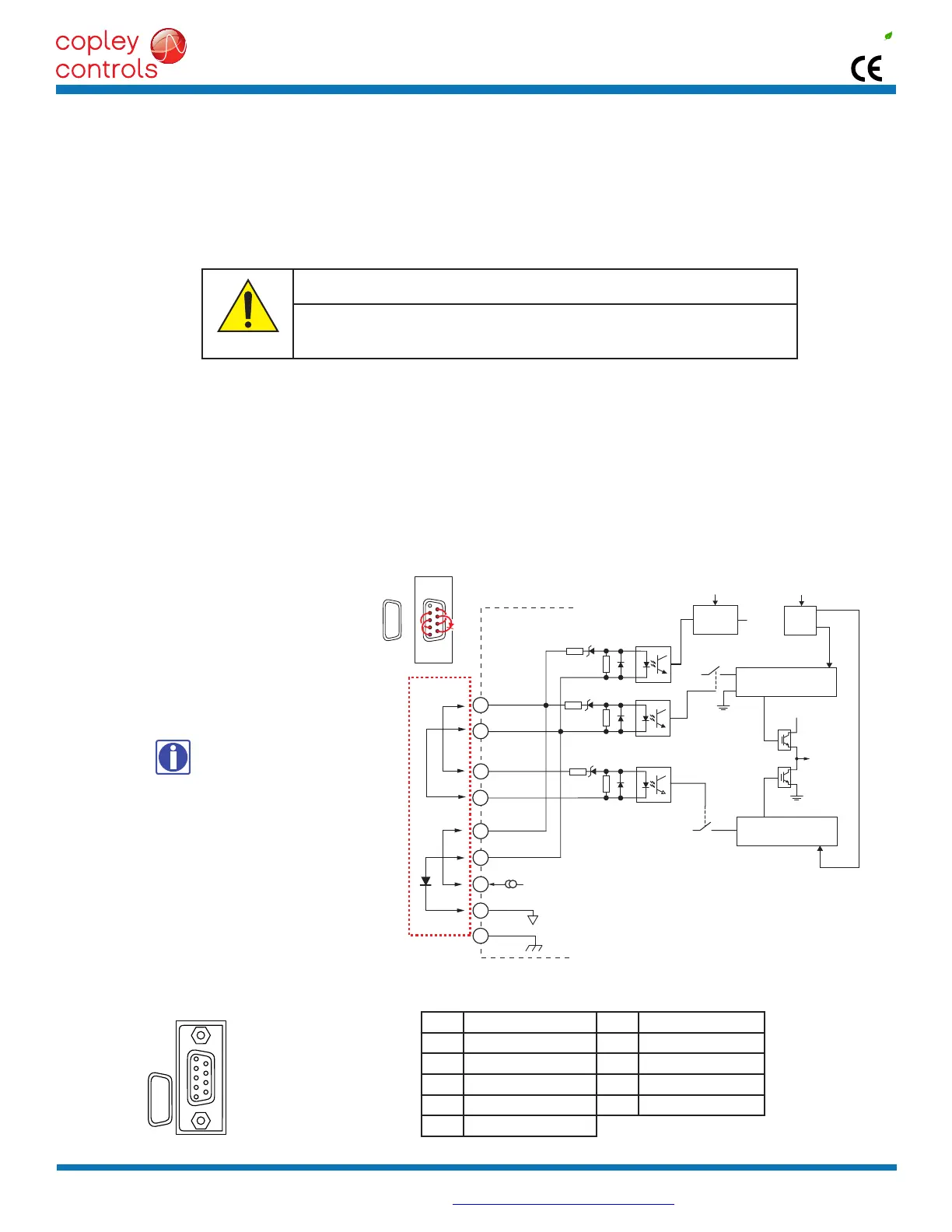
The800-1782providestheSafeTorqueOff(STO)functionasdenedinIEC61800-5-2.Threeopto-couplersareprovidedwhich,whende-energized,
preventtheupperandlowerdevicesinthePWMoutputsfrombeingoperatedbythedigitalcontrolcore.ThisprovidesapositiveOFFcapabilitythat
cannotbeoverriddenbythecontrolrmware,orassociatedhardwarecomponents.Whentheopto-couplersareactivated(currentisowingintheinput
diodes),thecontrolcorewillbeabletocontroltheon/offstateofthePWMoutputs.
SAFETORQUEOFF(STO)
STOBYPASS(MUTING)
InorderforthePWMoutputsofthe800-1782tobeactivated,currentmustbeowingthroughalloftheopto-couplersthatareconnected
totheSTO-IN1andSTO-IN2terminalsofJ6,andthedrivemustbeinanENABLEDstate.Whentheopto-couplersareOFF,thedriveisina
SafeTorqueOff(STO)stateandthePWMoutputscannotbeactivatedbythecontrolcoretodriveamotor.Thisdiagramshowsconnections
thatwillenergizealloftheopto-couplersfromaninternalcurrent-source.WhenthisisdonetheSTOfeatureisoverriddenandcontrolof
the output PWM stage is under control of the digital control core.
IfnotusingtheSTO
feature,theseconnectionsmustbemadeinorderforthe
800-1782tobeenabled.
STOBYPASSCONNECTIONS
STOCONNECTORJ6
J6SIGNALS
Currentmustow
throughalloftheopto-
couplersbeforethe
800-1782
canbeenabled
*STObypassconnectionsonthe800-1782and
XenusXELmodelsaredifferent.Ifbothdrivesare
installed in the same cabinet, the diode should be
wired as shown to prevent damage that could occur
iftheSTObypassconnectorsareinstalledonthe
wrongdrive.ThediodeisnotrequiredforSTO
bypass on the 800-1782 and can be replaced by a
wire between pins 7 and 9.
INSTALLATION
DANGER
RefertotheXenusPlusDual-AxisSTOUserManual
TheinformationprovidedintheXenusPlusDual-AxisSTOUserManualmustbe
consideredforanyapplicationusingthe800-1782drive’sSTOfeature.
Failuretoheedthiswarningcancauseequipmentdamage,injury,ordeath.
 Loading...