Do you have a question about the Corken D Series and is the answer not in the manual?
Offers quiet operation and increased durability in process gas applications.
Provides maximum thermal shock endurance for cylinder and head.
Step-cut design maximizes performance and life for non-lube service.
Simple design allows precise setting of end clearance for efficiency.
Spring-loaded PTFE seals self-adjust for normal wear.
Impregnated nitride coating provides superior corrosion and wear resistance.
Ensures maximum sealing capacity during packing life (T791/T891 models).
Durable cast iron provides superior resistance to corrosion and galling.
Self-reversing oil pump ensures proper lubrication; 10-micron filter.
Ensures proper ventilation, access, and compliance with safety and building codes.
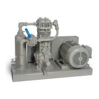
Essential for smooth operation; requires structural steel skid attached to concrete slab.
Proper design minimizes vibration transmission; use flexible connectors.
Prevents liquid entry into compressor; ASME code stamped with level switches.
Proper driver selection and installation is crucial; never operate without a flywheel.
Fill crankcase to full mark with appropriate industrial oil.
Key for leakage control and oil-free compression; use clean gas.
Must be installed on discharge side; material compatible with gas.
Provide protection against damage; includes low oil pressure, high temp switches.
Check cylinder bore and valve areas for rust or debris.
Ensure proper belt tension, sheave alignment, and flywheel runout.
Adjust oil pressure to approximately 20 psi minimum for normal service.
Comprehensive list of pre-start and post-start checks.
Test valves by closing inlet; inspect for damage, corrosion, or debris.
Seldom require replacement; damage due to corrosion or debris entry.
Replace rings and expanders; measure radial thickness for wear.
Depressurize, remove head, piston cap; adjust shims for clearance.
Adjust or replace packing when leakage is prevalent by tightening nuts.
Cylinders seldom require replacement; avoid damage from corrosion or debris.
Replace bearings by removing components; ensure proper alignment and lubrication.
Inspect gears, shaft bushing for corrosion or wear; replace O-rings.
List of available repair kits for various compressor models.
Defines base model codes for D791, T791, FD891, FT891.
Details for packing, crankcase, valves, materials, and coatings.
Explains how to build a model number from specification choices.
Key operating parameters like bore, stroke, displacement, and pressure.
Lists critical clearances and dimensions for assembly and maintenance.
Provides specific torque values for various bolts and fasteners.
Dimensional drawings and measurements for the D791 model.
Dimensional drawings and measurements for the D891 model.
Dimensional drawings and measurements for the T791 model.
Dimensional drawings and measurements for the FT891 model.
Parts breakdown for heads, valve holddowns, and valve assemblies.
Parts list and clearance data for piston assemblies.
Parts breakdown and assembly for various packing specifications.
Parts list for crosshead guide assemblies.
Parts list for connecting rod and crosshead assemblies.
Parts list for flywheel assembly components.
Parts list for crankcase assembly components.
Lists common issues and their potential causes.
Provides recommended steps to resolve compressor problems.
| Brand | Corken |
|---|---|
| Model | D Series |
| Category | Air Compressor |
| Language | English |