USB 3.1 Type-C
USB 3.0
HD AUDIO
POWER SW
RESET SW
POWER LED +
POWER LED –
8
7
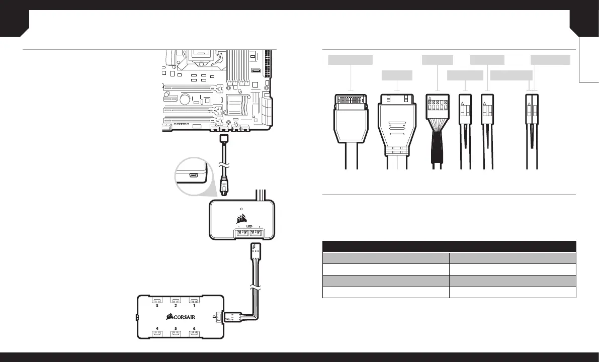
INSTALLING THE FRONT I/O CONNECTORS
ENGLISH
USING LIGHTING NODE PRO
1. Turn your system o prior to installing your
Lighting Node PRO.
2. Plug the mini USB cable into the back of the
Lighting Node PRO then plug the 9-pin end
into an available internal USB 2.0 header in
your system.
3. Connection Notes
> The Fan LED wiring must be connected
to the fan hub in the order you want the
lighting eects to be displayed.
> Fans must start at “1” and continue in series.
1 > 2 > 3 > 4 > 5 > 6
> Any fan not connected in series will break
communication and the RGB LED lighting
function will not work.
4. Mount the fan(s) to the location of your choice
in the chassis.
5. Find a location for the fan hub that allows
connection for all of the fans RGB LED cables
installed in your system to reach.
> The fan controller will also need to be
plugged into the fan hub for control of the
RGB LED lighting.
6. Mount the fan hub with the provided
mounting strips.
FREQUENTLY ASKED QUESTIONS
1. Does the polarity matter with the I/O panel’s power and reset header?
No, only the LED headers.
2. Who should I contact if I received my case damaged or one of the fans is no longer working?
Please go to support.corsair.com and request an RMA so that we can replace
the damaged part(s).
3. Where can I mount a fan?
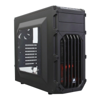
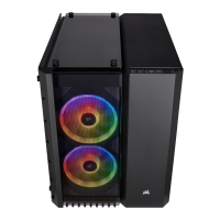
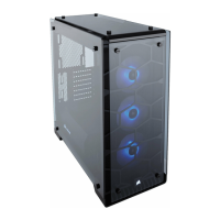
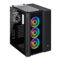
To learn more about this case visit the product page at corsair.com.
Fan mount locations
Front 3x0mm / 2x0mm
Top x20mm / 2x0mm
Bottom 2x20mm / 2x0mm
Rear x20mm / x40mm
 Loading...