6.3 Isolation
¡
When you run a Hi-Pot test as receiving inspection, gradually in-
crease the voltage to start. When you shut down, decrease the
voltage gradually by using a dial. Please avoid a Hi-Pot tester
with a timer because, when the timer is turned ON or OFF, it may
generate a voltage a few times higher than the applied voltage.
¡
When you test a unit for isolation between the input and output or
between the output and the terminal FG, short-circuit between the
output and the terminals RCG, PGG and AUXG.
6.4 Auxiliary Power (AUX)
¿
PBA300F, PBA600F, PBA1000F and PBA1500F
¡
The power supplies can generate an auxiliary power (AUX: 12V
0.1A) from CN3 to provide for remote ON/OFF and attached cir-
cuits.
¡
AUX circuit is isolated from other (input, output, FG, RC and PG)
circuits.
¡
Please do not draw a current of 0.1A or higher from the auxil-
iary power because doing so could damage the internal circuits or
cause malfunction.
When you connect a DC-DC converter, a current a few times
higher than normal current may ow at start-up. Please check the
current.
6.5 External Component (Noise Filter)
¿
PBA1500F
¡
You can have the power supplies comply with FCC Part 15 class
B and EN55022-B by connecting an external noise lter.
Examples of Constant Values of the External Noise Filter
L 1 : 0.45mH L 2 : 0.45mH
C1 : 0.1 F C2 : 0.1 F C3 : 0.1 F
C4 : 4700pF C5 : 4700pF
R1 : 2M
W
R2 : 2M
W
6 Others
6.1 Output Current Monitor
¿
PBA300F, PBA600F, PBA1000F and PBA1500F
¡
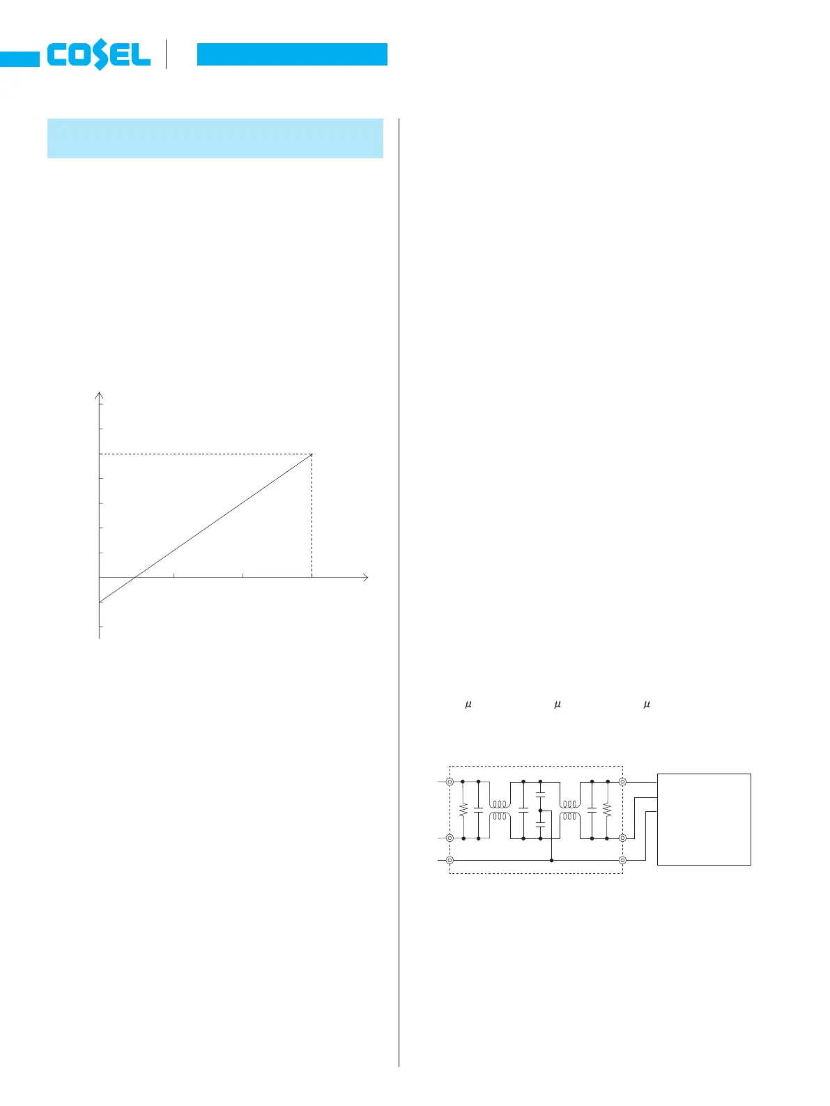
You can monitor an output current by measuring a voltage be-
tween the terminal CB and the terminal -S on either CN1 or CN2.
¡
Fig.6.1 shows the relationship between the voltage of the terminal
CB and the output current.
Fig.6.1 shows a typical characteristic of PBA1500F-5. Please
contact us for the characteristics of the other models.
The output current shown in Fig.6.1 should be used only as a
guide.
¡
Please note the followings when measuring the voltage of the ter-
minal CB.
-
Wire carefully to avoid malfunction caused by noise.
-
Use a measuring instrument whose input impedance is 500
W
or more.
-
Do not short-circuit between CB terminal and -S terminal. Do-
ing so could cause a failure.
6.2 External Capacity
¿
PBA10F, PBA15F, PBW15F, PBA30F and
PBW30F
¡
When a capacitor with large capacity is connected to the load
side, a power supply may stop or start hunting. Please contact us
for details.
Unit type
Instruction Manual
A-42
PB


 To Next Page