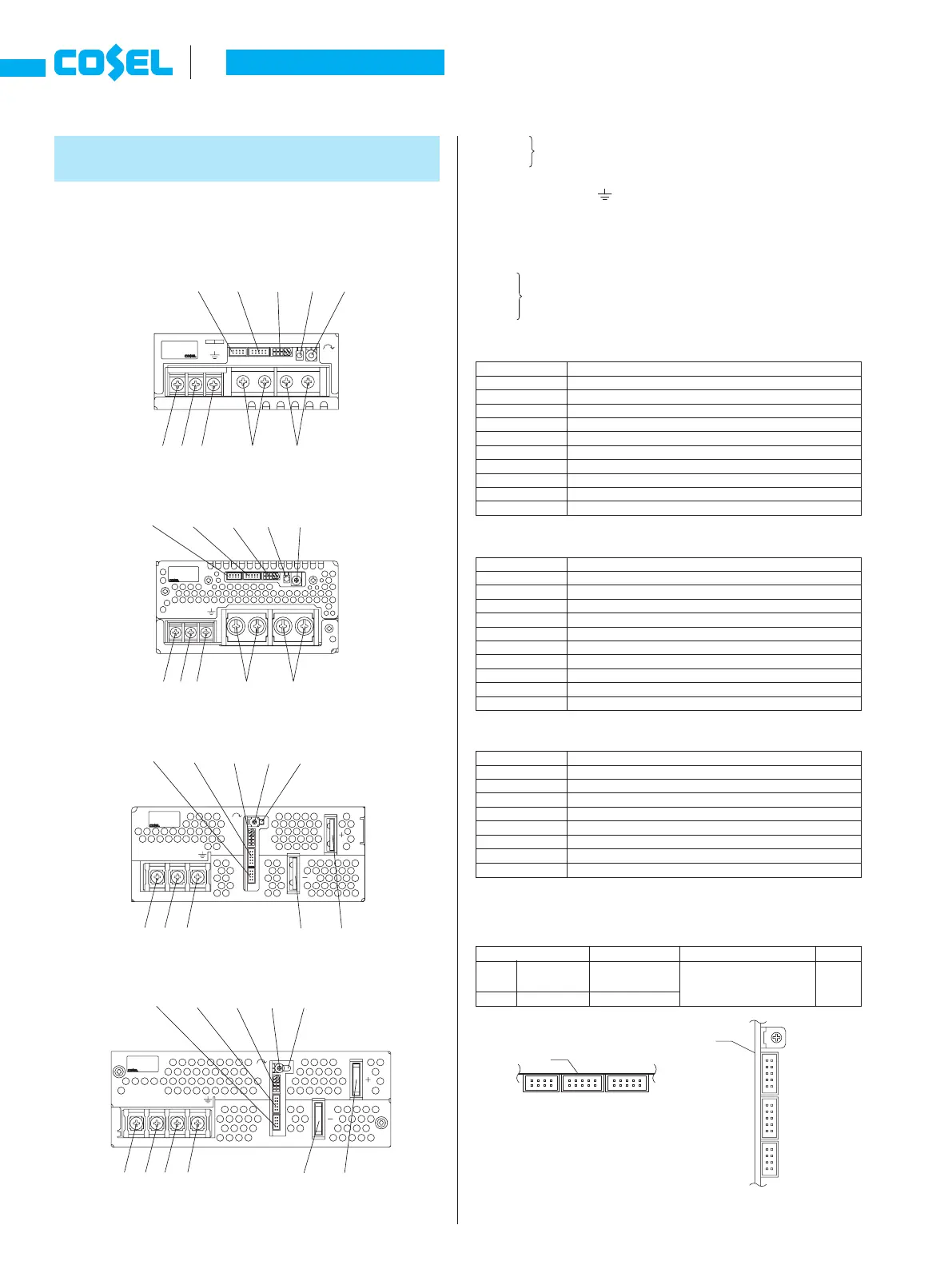
1 Terminal Blocks
1
AC (L)
Input Terminals AC85 - 264V
f
47 - 63Hz
2
AC (N) (M4)
3
NC
4
Frame ground (M4
)
5
-Output
6
+Output
7
LED
8
Output voltage adjustable potentiometer
9
CN1
0
CN2 Connectors
å
CN3
*
Please see Optional Parts for dedicated harnesses.
*
The following information covers PBA300F - 1500F. Please see External
View for PBA10F - 150F and PBW15F - 50F.
Unit type
Instruction Manual
A-34
PB
¿
PBA1000F
Pin Conguration and Functions of CN1
Pin No.
1
2
3
4
5
6
7
8
9
10
Function
+M :
Self sensing terminal. (Do not wire for external connection.)
+S : +Sensing
-M :
Self sensing terminal. (Do not wire for external connection.)
-S : -Sensing
VB : Voltage balance
CB : Current balance
TRM : Adjustment of output voltage
-S : -Sensing
RC2 : Remote ON/OFF
RCG : Remote ON/OFF (GND)
Pin Conguration and Functions of CN3
Pin No.
1
2
3
4
5
6
7
8
Function
-S : -Sensing
-S : -Sensing
AUX : Auxiliary output (12V 0.1A)
RC1 : Remote ON/OFF
AUXG : Auxiliary output (GND)
N.C. : No connection
PG : Alarm
PGG : Alarm (GND)
Matching connecters and terminals on CN1, CN2 and CN3
Connector Housing Terminal
Mfr.
CN1
CN2
CN3
S10B-PHDSS
S8B-PHDSS
PHDR-10VS
PHDR-08VS
Reel : SPHD-002T-P0.5
Loose : BPHD-001T-P0.5
J.S.T.
Pin Conguration and Functions of CN2
Pin No.
1
2
3
4
5
6
7
8
9
10
Function
+M :
Self sensing terminal. (Do not wire for external connection.)
+S : +Sensing
-M :
Self sensing terminal. (Do not wire for external connection.)
-S : -Sensing
VB : Voltage balance
CB : Current balance
TRM : Adjustment of output voltage
-S : -Sensing
RC2 : Remote ON/OFF
RCG : Remote ON/OFF (GND)
*
Common signs among CN1, CN2 and CN3 such as -S represent the same
potential.
Connector pin numbers
¿
PBA600F
¿
PBA1500F
¿
PBA300F
1 2
7 89
4
5 6
å 0
1 2
7 89å
0
4
5 6
1 2
5 6
789å
0
4
1 2 3 5 6
789å
0
4
¿
PBA300F/600F
¿
PBA1000F/1500F
PCB
2
1
CN3 CN2 CN1
10
9
2
1
10
9
2
1
8
7
1
9
1
9
1
7
2
CN1
PCB
CN2
CN3
10
2
10
2
8
H
V. ADJ
( N)
( L)
AC
FG
AC
AC
(L) FG
AC
CN1
H
(N)
CN3
CN2
V. ADJ
( N)
V. ADJ
FGNC
AC
( L)
AC
CN1
CN2
CN3