3 Peak Current
4.1 Series Operation
¡
You can use a power supply in series operation. The output cur-
rent in series operation should be lower than the rated current of a
power supply with the lowest rated current among power supplies
that are serially connected. Please make sure that no current ex-
ceeding the rated current ows into a power supply.
4 Series/Parallel
Operation
¿
PBA300F-24, PBA600F-24, PBA1000F-24
and PBA1500F-24/36
¡
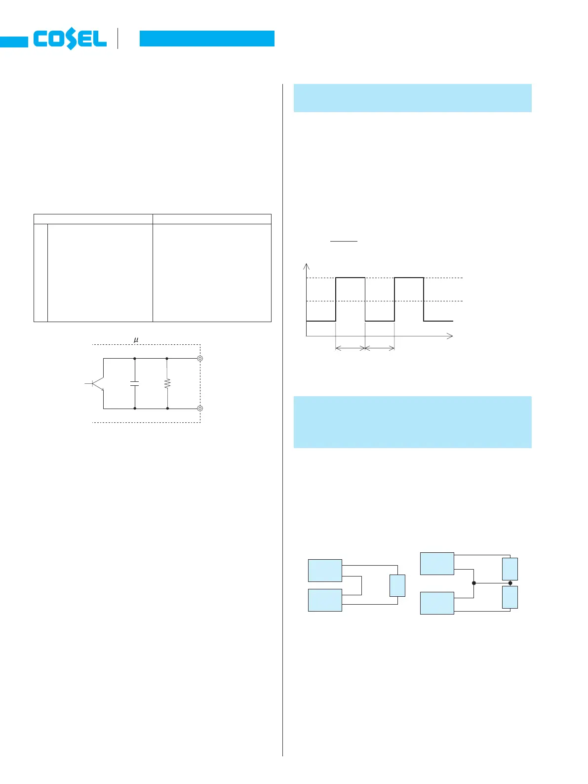
The units can generate the peak current under the following con-
ditions.
-
AC170 - 264V
-
t1
[
10 [sec]
-
Ip
[
Rated peak current
-
Iave
[
Rated current
-
Duty=
t1
X
100 [%]
[
35%
t1+t2
2.9 Alarms
¿
PBA300F, PBA600F, PBA1000F and PBA1500F
¡
Alarms (PG signal) are generated from CN3. Please see Table
2.2 for the functions of the alarms. The objective of the PG sig-
nals is to detect whether or not a certain function of a power sup-
ply is working. It takes several seconds to generate the alarm
signals and the timing when the alarm signals are generated is in-
consistent. Please check if the objective of the alarm is achieved.
¡
Please note the followings when you use the alarms (PG signal).
1
The time it takes until the PG signals turn ”High” vary depending
on models and conditions.
PBA300F and PBA600F
…..
less than 1 second
PBA1000F and PBA1500F
…..
less than 10 second
2
If the output voltage is turned off through a remote ON/OFF cir-
cuit, the PG signals turn ”High”.
3
The PG signal may turn ”High”, if the output current becomes
10% or below of the rated current in parallel operation (in this
case, the fan also stops).
4
If the output voltage is decreased to almost 0V or decreased
rapidly through an external adjustment mechanism when load is
light, The PG signal may turn ”High”.
¡
The PG signal (Alarm) circuit is isolated from input, output, FG,
RC and AUX.
Unit type
Instruction Manual
A-38
PB
Fig.4.1 Examples of connecting in series operation
Fig.3.1 Peak current
Load
(a) (b)
Load Load
Power
Supply
+
-
Power
Supply
+
-
Power
Supply
+
-
+
-
Power
Supply
[A]
Output current
Ip:Peak current
Iave:Average current
t1 t2
Table 2.2 Description of the alarms (PG signal)
Alarm Output of Alarm
PG
The PG signals are ”Low” when
th e p o w e r s uppl y o p e r ates
normally.
The signals turn ”High” when the
fan stops or the power supply
stops as a result of output voltage
decreas e/st op, activat ion of
thermal protection, overvoltage
p r o t e c t i o n o r o v e r c u r r e n t
protection functions.
Open collector method
Good: Low
(0.5V max at 10mA)
Bad : High or Open
50V 10mA max
100kW0.1 F
PG
PGG
Fig.2.6 Internal circuit of PG