5.1 Installation
¡
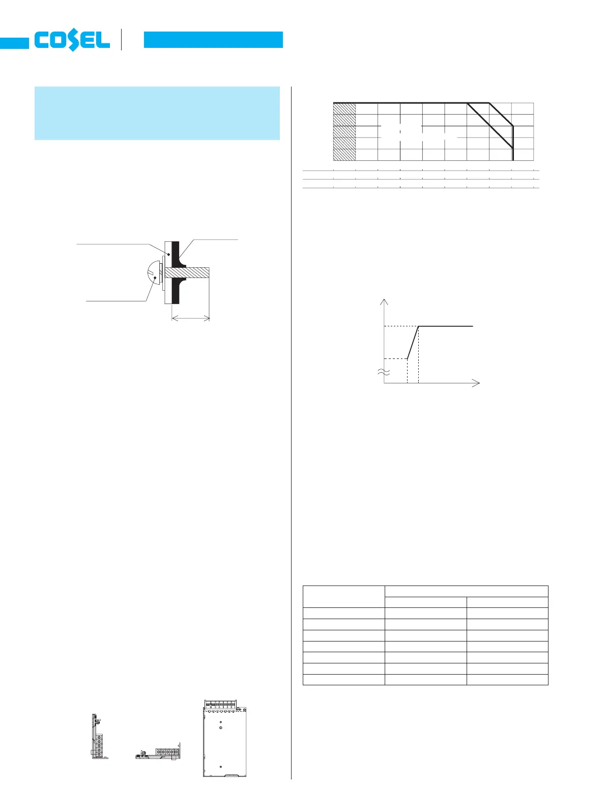
Do not insert a screw more than 6mm from the outside of a power
supply to keep enough insulation distance between the screw and
internal components.
5 Assembling and
Installation
¿
PBA10F, PBA15F, PBW15F, PBA30F,
PBW30F, PBA50F, PBW50F, PBA75F,
PBA100F and PBA150F
¡
If you use two or more power supplies side by side, please keep
a sufcient distance between them to allow enough air ventilation.
Ambient temperature around each power supply should not ex-
ceed the temperature range shown in the derating curve.
¿
PBA300F, PAB600F, PBA1000F and PBA1500F
¡
The power supplies have a built-in forced cooling fan. Do not
block ventilation at the suction side (terminal block side) and its
opposite side (fan installation side).
If you need to secure a power supply by screws, securely x it,
taking into consideration of its weight. You can install it in any di-
rection.
¡
If you use a power supply in a dusty environment, it can give a
cause for a failure. Please consider taking such countermeasures
as installing an air lter near the suction area of the system to pre-
vent a failure.
5.2 Derating
¿
PBA10F, PBA15F, PBW15F, PBA30F,
PBW30F, PBA50F, PBW50F, PBA75F,
PBA100F and PBA150F
¡
Mounting Method
¡
Derating Curve
*
Specications for ripple and ripple noise changes in the shaded
area.
¿
PBA10F, PBA15F, PBW15F, PBA30F and
PBW30F
¡
Input Voltage Derating Curve
Input voltage derating curve is shown in Fig.5.2.
¿
PBA300F, PAB600F, PBA1000F and PBA1500F
¡
Ambient Temperature Derating Curve
Derating curve depending on an ambient temperature (tempera-
ture of air sucked in for a cooling purpose) is shown in Fig.5.3.
*
Specications for ripple and ripple noise changes in the shaded
area.
¡
Standard for Cooling
¿
PBA10F, PBA15F, PBW15F, PBA30F,
PBW30F, PBA50F, PBW50F, PBA75F,
PBA100F and PBA150F
¡
Please make sure that the temperature of Point A (see External
View) falls under a temperature specied in Table 5.1.
¡
The temperatures shown in Table 5.1 for PBA10F, PBA15F,
PBW15F, PBA30F and PBW30F are those for their capacitors.
¡
Point A is engraved on the chassis of PBA50F, PBW50F, PBA75F,
PBA100F and PBA150F.
Table 5.1 Temperatures of Point A
Unit type
Instruction Manual
A-40
PB