Do you have a question about the Covidien ForceTriad and is the answer not in the manual?
Explains symbols and terms used in the manual for clarity and consistency.
Details Covidien's warranty coverage for the ForceTriad Energy Platform and related products.
Outlines the terms and conditions for using the system's software.
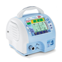
Provides an overview of the ForceTriad energy platform's design and capabilities.
Illustrates and describes the components and connectors on the front of the device.
Illustrates and describes the components and connectors on the back of the device.
Explains touchscreen interfaces and common symbols used in the system.
Details the various operating modes and their functions for different surgical applications.
Provides essential safety warnings and instructions for setting up the system.
Details precautions to prevent fires and explosions, especially in the presence of flammable anesthetics.
Covers safety aspects related to instrument connections and system usage.
Addresses considerations for patients with IEDs and safety during cleaning.
Highlights critical safety information regarding patient return electrodes and RF burns.
Outlines potential hazards and safety precautions specific to laparoscopic surgery.
Provides safety warnings and cautions for Bipolar and LigaSure modes of operation.
Covers safety precautions during servicing and the use of shunt cords.
Addresses safety considerations when conductive fluids are used in the surgical site.
Presents a system block diagram and a key to its various cable connections.
Explains the general functions of the electrosurgical unit and LigaSure system.
Describes how the system senses and adjusts for tissue impedance.
Details the function and operation of the Return Electrode Monitor system.
Explains how REM alarms are activated and the safety features associated with them.
Describes the operational principles of the HVDC power supply board.
Explains the functions of the Radio Frequency Printed Circuit Board Assembly.
Details the sensor circuits and the principles of operation for the Steering Relay PCBA.
Explains the circuitry of the Display Printed Circuit Board Assembly.
Describes the audio and footswitch circuitry on the respective PCBA.
Explains the functions of the Controller PCBA and its role in system management.
Details the operation of DSPs and data converters within the system.
Provides general specifications including dimensions, weight, cooling, and display.
Specifies environmental and operational parameters for the system.
Details internal memory capacity and specifications for system audio tones.
Provides detailed specifications for the REM system's resistance monitoring.
Outlines autobipolar feature specifications and measurement accuracy tables.
Specifies duty cycle limits, leakage current values, and input power requirements.
Details the requirements for the system's AC power cord.
Specifies input frequency, current draw, backup power, and grounding connections.
Lists relevant safety and classification standards the system complies with.
Provides guidance and declarations regarding electromagnetic emissions and immunity.
Details maximum output power and available power settings for various modes.
Describes the specific output waveforms used in different operating modes.
Presents graphical data illustrating power output under varying load conditions.
Guides users through initial setup procedures and system power-up sequence.
Details system functions like display brightness, logs, service access, and restore options.
Explains how to configure system language and set the current time and date.
Describes enabling/disabling system features like Autobipolar and footswitching.
Provides instructions for entering and exiting Demo Mode for practice scenarios.
Step-by-step instructions for physically setting up the ForceTriad energy platform.
Guides through the calibration process, including common symbols and levels.
Outlines the sequence of calibration steps and defines different calibration levels.
Details the calibration procedures for system utilities like date, time, brightness, and touchscreens.
Explains the calibration steps for RF leakage, current, and voltage measurements.
Covers calibration procedures for external sensors like Autobipolar and REM.
Describes annual safety checks to ensure proper system function and safety.
Lists the necessary equipment for performing tests and calibrations.
Provides guidance on inspecting external and internal system components.
Details procedures for testing power delivery and outputs across various modes.
Explains how to test for high and low frequency leakage currents.
Covers ground bond testing procedures and docking the system to Valleylab Exchange.
Guides on inspecting the system for issues and responding to displayed error messages.
Lists and explains various system errors, including non-recoverable ones.
Provides troubleshooting steps for specific error codes related to system components.
Details troubleshooting steps for a wide range of error codes related to software and hardware.
Step-by-step instructions for removing and reinstalling the front panel assembly.
Details the process for safely replacing system fuses.
Provides instructions for replacing the system's internal battery.
Guides on how to replace the Low-Voltage Power Supply component.
Instructions for replacing the Footswitch/Audio Printed Circuit Board Assembly.
Step-by-step guide for replacing the Controller Printed Circuit Board Assembly.
Instructions for replacing the High-Voltage DC Printed Circuit Board Assembly.
Details the procedure for replacing the Radio Frequency Printed Circuit Board Assembly.
Provides instructions for removing and installing the Steering-Relay PCBA.
Step-by-step guide for replacing the Display Printed Circuit Board Assembly.
Instructions for removing and installing the barcode scanner component.
Guides on replacing various output receptacles on the front panel.
Details the procedure for replacing the barcode scanner cables.
Instructions for replacing system displays (LCD/touch screens) and their cables.
Provides steps for replacing the system cooling fans.
Instructions for replacing the scan stand label.
Outlines manufacturer responsibilities and recommendations for routine system checks.
Provides instructions for safely cleaning the system's surfaces.
Details the process for returning the system for service and contacting support.
Information on how to order replacement parts, including required system details.
Lists replaceable components and emphasizes ESD precautions during handling.
Provides guidance on replacing various cable assemblies using wiring schematics.
| Type | Electrosurgical Generator |
|---|---|
| Brand | Covidien |
| Model | ForceTriad |
| Footswitch | Yes |
| Voltage | 100-240 VAC |
| Output Power | 300 watts |
| Modes | Cut, Coag |
| Frequency | 50/60 Hz |
| Argon Beam Coagulation | Optional |