page 7
6. Wiring.
WARNING: Turn o circuit breakers to current xture
from breaker panel and be sure switch is turned to
the OFF position.
CAUTION: Be sure outlet box is properly grounded or
that a ground wire (GREEN or Bare) is present.
Make sure all electrical connections comply with Local
Codes or Ordinances and the National Electrical Code.
If you are unfamiliar with electrical wiring or if the
house/building wires are dierent colors than those
referred to below, please use a qualied electrician.
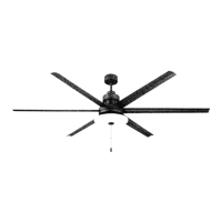
Note: Excess lead wire length from the fan can be cut to
the desired length and then stripped.
When fan is secured in place on the hanging bracket,
electrical wiring can be made as follows:
Connect BLACK wire from fan to BLACK wire from
ceiling with wire connector provided.
Connect WHITE wire from fan to WHITE wire from
ceiling with wire connector provided.
Connect all GROUND (GREEN) wires together from
fan to BARE/GREEN wire from ceiling with wire
connector provided.
* Wrap each wire connector separately with electrical
tape as an extra safety measure.
[PLEASE NOTE: Wall and/or handheld remote
control must be used for fan to operate. If you do not
wish to use the wall control, please proceed to
Section 7 on the following page to continue with fan
installation.]
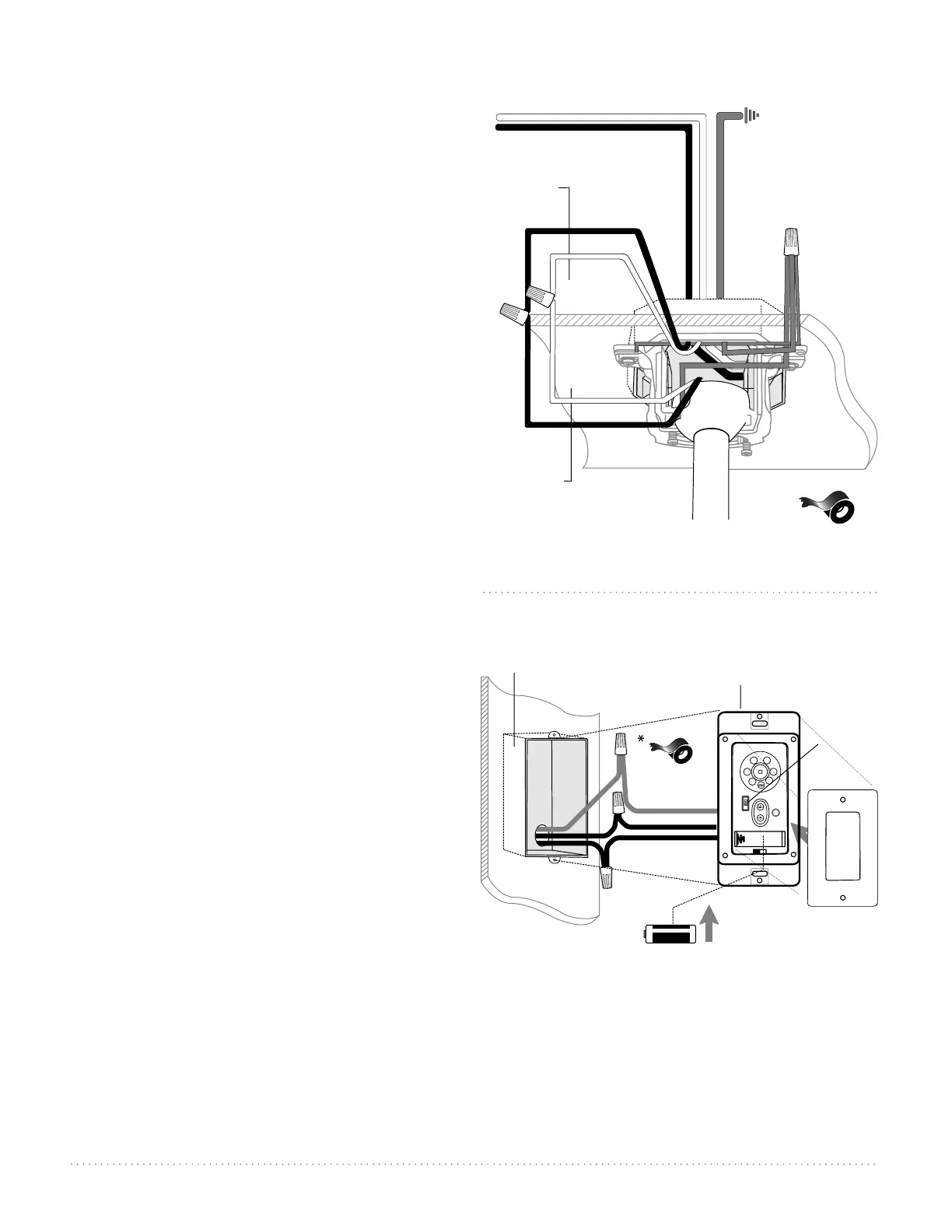
To install wall control, remove existing wall switch.
Wire one of the wall controls with wire connectors
provided as shown in diagram at right.
*Wrap each wire connector separately with electrical
tape as an extra safety measure. Gently push wires
and taped wire connectors into outlet box.
Install one 12-volt battery (included) in wall control.
IMPORTANT: Wall control will not function unless
battery is installed.
WARNING: Battery is to be inserted with the correct
polarity.
Since this fan comes with an LED light kit, the
dimmer switch (labeled D and ON) has been pre-set
to the "ON" position (D). If you do not wish to have
dimming capability, please move the switch to the
"OFF" position (ON).
Select a faceplate (almond or white) and press rmly
onto front of wall control. Attach wall control to
outlet box and secure with screws from original wall
switch. Attach wall plate (included) to wall control
using 2 screws provided with the wall control.
(wiring for wall control)
black (OUT to fan)
green
black
(AC IN from
breaker box)
black
(TO POWER supply)
black
green/
bare
ground
green/
bare
ground
outlet box
wall
control
12V battery
dimmer
switch
plate
I
II
IV
VI
III
V
(wiring for fan)
black
black
white
white
black supply wire
ground
(green
or bare)
white supply wire
*
from
ceiling
from fan
ground
(green or bare)