page 6
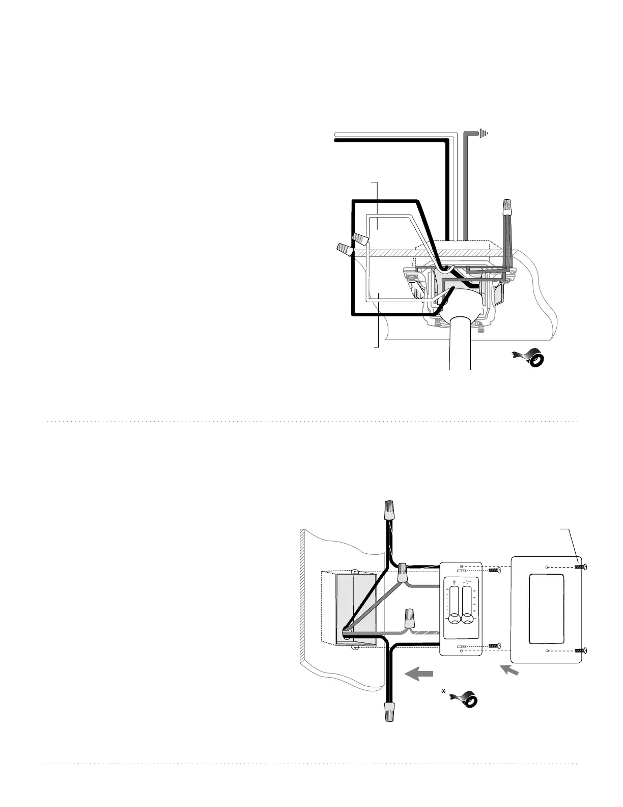
6. Wiring.
WARNING: Turn off circuit breakers to current fixture
from breaker panel and be sure switch is turned to the
OFF position.
CAUTION: Be sure outlet box is properly grounded and that
a ground wire (GREEN or Bare) is present.
Make sure all electrical connections comply with Local
Codes or Ordinances and the National Electrical Code. If you
are unfamiliar with electrical wiring or if the house/building
wires are different colors than those referred to in the
diagram to the right, please use a qualified electrician.
Note: Excess lead wire length from the fan can be cut to the
desired length and then stripped.
When fan is secured in place on the hanging bracket,
electrical wiring can be made as follows:
Connect BLACK and BLUE wires from fan to BLACK wire
from ceiling. Connect WHITE wire from fan to WHITE
wire from ceiling. Connect all GROUND (GREEN) wires
together from fan to BARE/GREEN wire from ceiling. Use
wire connectors provided when making connections.
If you intend to control the fan light with a separate light
switch connect BLUE wire from fan to the BLACK (or
RED) supply from the independent switch.
* Wrap each wire connector separately with
electrical tape as an extra safety measure.
7. Wiring - Wall Control
Remove existing wall switch. Wire the wall
control as shown in diagram at right.
Connect BLACK/WHITE wire from wall control
to BLACK (AC IN L) wire in outlet box. Connect
BLACK wire from wall control to BLACK (AC IN
N) wire from fan (inside the outlet box).
Connect BLUE wire from wall control to BLUE
wire from light in the outlet box. Connect
GREEN/YELLOW ground wire from wall control to
ground wire in the outlet box.
Use wire connectors
provided when making connections.
*Wrap each wire connector separately with
electrical tape as an extra safety measure.
Gently push wires and taped wire connectors
into outlet box.
Attach wall control to outlet box and secure
with screws from original wall switch. Attach
plate (included) to wall control using 2 screws
provided with the wall control.
plate
wall control
plate
screw
outlet box
BLACK
(AC IN N
from fan)
BLACK
BLUE
GREEN/
YELLOW
BLACK
(AC IN L)
BLACK/WHITE
green/
bare
ground
BLUE
black
black
white
white
black supply wire
ground
(green
or bare)
white supply wire
*
from ceiling
from fan
ground
(green or bare)