OPERATING INSTRUCTIONS AND PARTS LIST FOR
MODEL NUMBER 103.23340
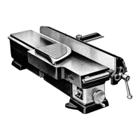
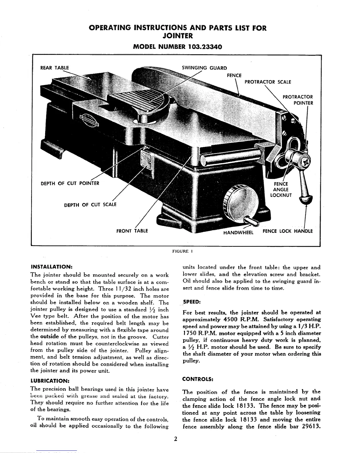
REAR TABLE
SWINGING GUARD
FENCE
PROTRACTOR SCALE
PROTRACTOR
POINTER
DEPTH OF CUT POINTER FENCE
ANGLE
DEPTH OF CUT SCALE
FRONT TABLE
HANDWHEEL FENCE LOCK HANDLE
FIGURE I
INSTALLATION:
The jointer should be mounted securely on a work
bench or stand so that the table surface is at a com-
fortable working height. Three 11/32 inch holes are
provided in the base for this purpose. The motor
should be installed below on a wooden shelf. The
jointer pulley is designed to use a standard ]/_ inch
Vee type belt:. After the position of the motor has
been established, the required belt length may be
determined by measuring with a flexible tape around
the outside of the pulleys, not in the groove, Cutter
head rotation must be counterclockwise as viewed
from the pulley side of the jointer. Pulley align-
ment, and belt tension adjustment, as well as direc-
tion of rotation should be considered when installing
the jointer and its power unit.
LUBRICATION:
The precision ball bearings used in this jointer have
beet_ packed with grease slid sealed at the factory.
They should require no further attention for the life
of the bearings.
To maintain smooth easy operation of the controls,
oil should be applied occasionally to the following
units located under the front table: the upper and
lower slides, and the elevation screw and bracket,
Oil should also be applied to the swinging guard ih-
sert and fence slide from time to time.
SPEI:D:
For best results, the iointer should be operated at
approximately 4500 R.P.M. Satisfactory operating
speed and power may be attained by using a I/3 H.P.
1750 R.P.M. motor equipped with a 5 inch diameter
pulley, if continuous heavy duty work is planned,
a _ H.P. motor should be used. Be sure to specify
the shaft diameter of your motor when ordering this
pulley.
CONTROLS:
The position of the fence is maintained by the
clamping action of the fence angle lock nut and
the fence slide lock 18133. The fence may be posi-
tioned at any point across the table by loosening
the fence slide lock 18133 and moving the entire
fence assembly along the fence slide bar 29613.
 Loading...