14
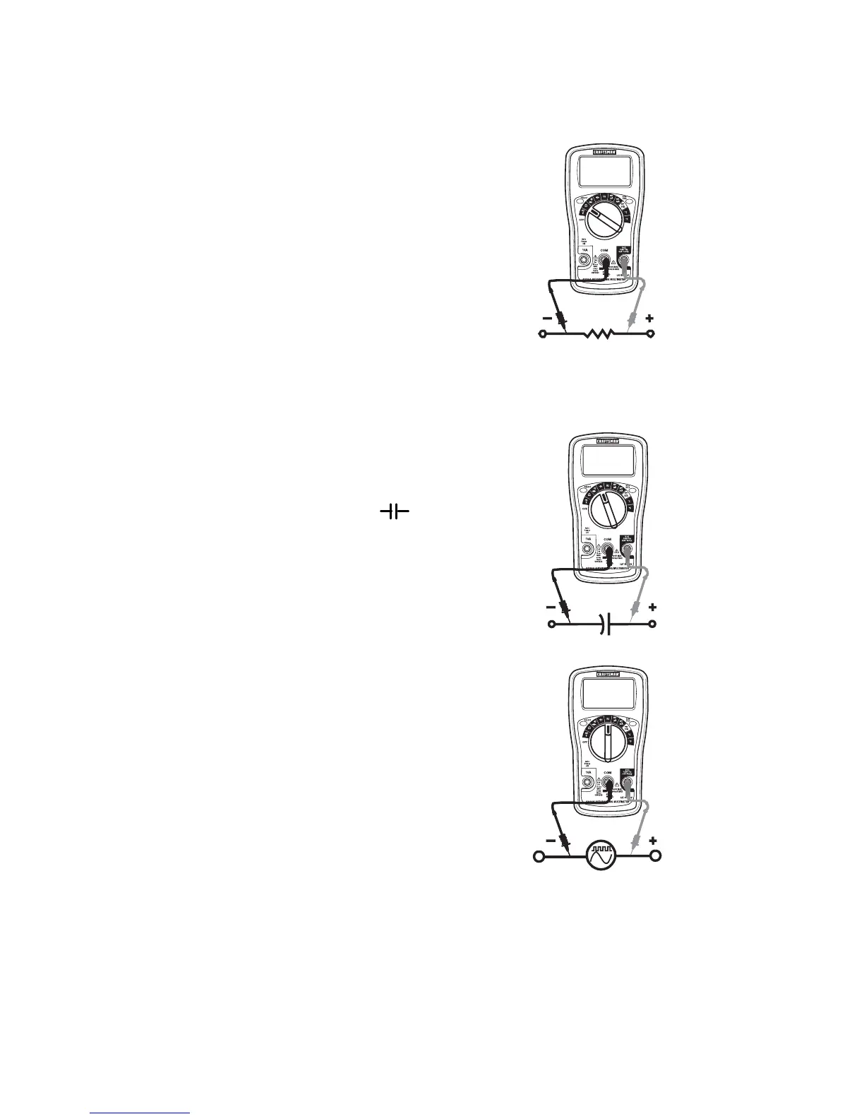
RESISTANCE MEASUREMENTS
1. Insert the black test lead banana plug into
the negative COM jack and the red test lead
banana plug into the positive jack.
2. Set the function switch to the position.
3. Touch the test probe tips across the circuit or
part under test. It is best to disconnect one
side of the part under test so the rest of the
circuit will not interfere with the resistance
reading.
4. Read the resistance in the display.
CAPACITANCE MEASUREMENTS
1. Insert the black test lead banana plug into the
negative COM jack and the red test lead
banana plug into the positive CAP jack.
2. Turn the rotary switch to the position.
3. Touch the test probes to the circuit or device
under test and read the capacitance on the
display.
FREQUENCY MEASUREMENTS
1. Insert the black test lead banana plug into
the negative COM jack and the red test lead
banana plug into the positive HZ jack.
2. Turn the rotary switch to the Hz position.
3. Touch the test probes to the circuit or under
test and read the frequency or duty cycle on
the display.


 To Next Page