1 GENERAL POWER TOOL
SAFETY WARNINGS
WARNING
Read all safety warnings, instructions, illustrations and
specifications provided with this power tool.Failure to
follow the warnings and instructions may result in electric
shock, fire and/or serious injury.
Save all warnings and instructions for future reference.
The term "power tool" in the warnings refers to your mains-
operated (corded) power tool or battery-operated (cordless)
power tool.
2 DESCRIPTION
2.1 PURPOSE
This machine is used for domestic lawn mowing. The cutting
blade must be approximately parallel to the ground. All four
wheels must touch the ground while mowing.
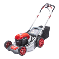
2.2 OVERVIEW
Figure 1-11
1
Start button
2
Start handle
3
Self-propel drive lever
4
Upper handle
5
Lower handle
6
Grass catcher
7
Rear discharge flap
8
Height adjustment lever
9
Battery compartment flap
10
Mulch plug
11
Side discharge chute
12
Handle hole
13
Handle bolt
14
Handle nut
15
Handle pin
16
Grass catcher handle
17
Grass catcher hook
18
Rear flap rod
19
Side discharge flap
20
Pivot
21
Safety key
22
Battery pack
23
Battery capacity indicator
24
Self-propel speed control
25
Blade bolt
26
Spacer
27
Blade
28
Battery release button
29
Turbo button
3 INSTALLATION
WARNING
Do not use accessories that are not recommended by the
manufacturer.
WARNING
Do not put in the safety key or the battery pack until you
finalised the assembly of all the parts.
3.1 UNPACK THE MACHINE
WARNING
Make sure that you correctly assemble the machine before
use.
WARNING
• If parts of the machine are damaged, do not use the
machine.
• If you do not have all the parts, do not operate the
machine.
• If parts are damaged or missing, contact the service
center.
1. Open the package.
2. Read the documentation provided in the box.
3. Remove all the unassembled parts from the box.
4. Remove the machine from the box.
5. Discard the box and packing material in compliance with
local regulations.
WARNING
For your personal safety, do not insert battery before the
tool is assembled completely.
3.2 INSTALL THE UPPER HANDLE
Figure 2
1. Align the holes in the upper handle and the lower handle.
2. Put the bolts through the holes.
3. Tighten the knobs onto the bolts.
4. Do the same operation on the other side.
3.3 UNFOLD THE LOWER HANDLE
Figure 3
1. Pull up on the handle holes to release the lower handles.
2. Fold the lower handle up until the handle pins lock into
position.
4
English
EN
 Loading...