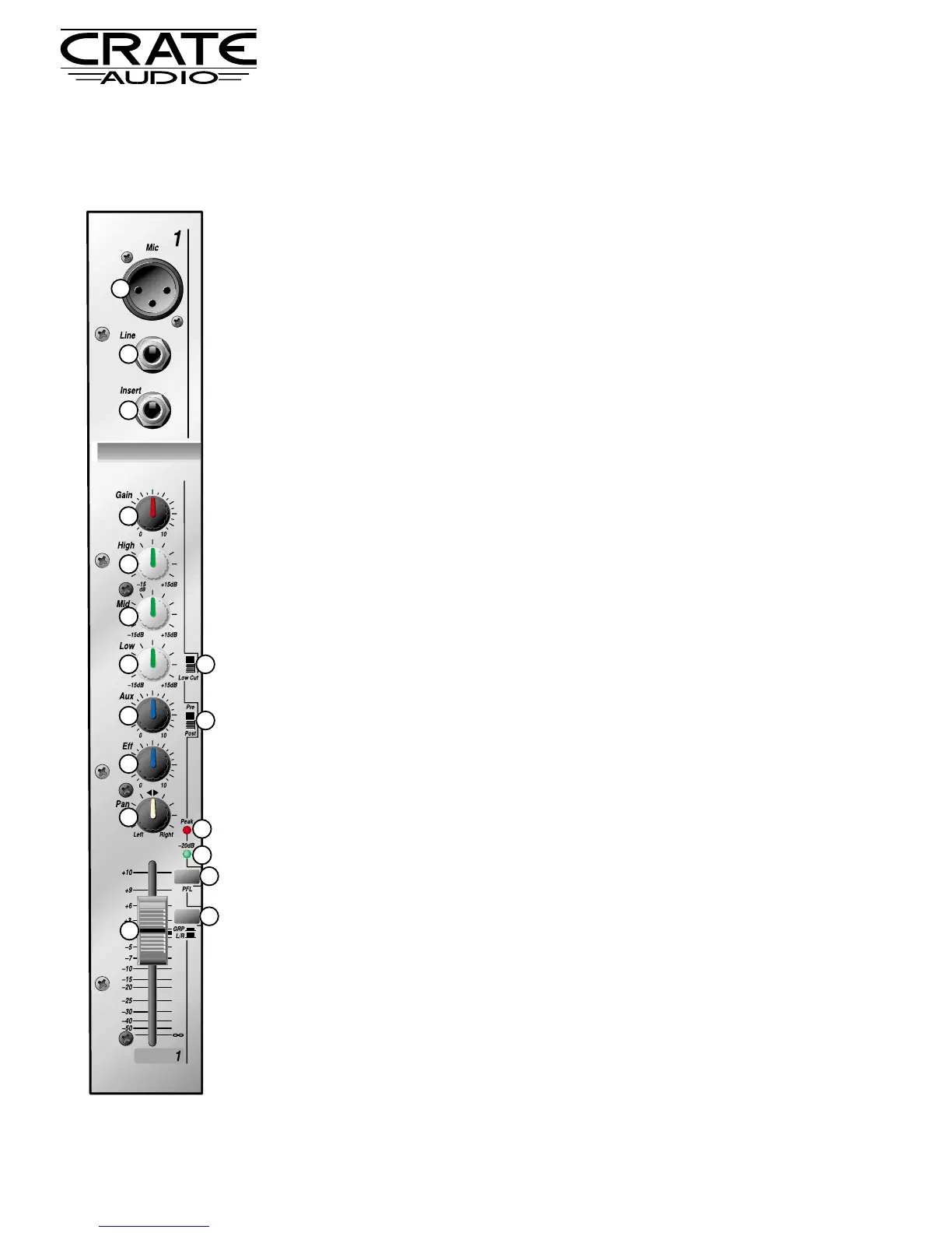
1 MIC IN: An XLR jack for balanced Low-Z mic inputs. When using a condenser mic,
the Phantom Power switch (#63, rear panel - page 7) must be activated.
2 LINE: A Tip/Ring/Sleeve 1/4” jack for balanced Hi-Z mics, instruments, drum machines,
and similar high impedance line level signals.
3 INSERT: A Tip/Ring/Sleeve 1/4” jack for adding an external signal processor to the
channel. The wiring diagram for this jack is shown on page 13. Applications informa-
tion is shown on pages 8 – 13.
4 GAIN: Adjusts the input signal level. Proper setting causes the Peak LED (#13) to flash
at strong input signals.
5 HIGH: Controls the high frequency level for the channel. Allows ±15dB @ 12kHz.
Shelving type.
6 MID: Controls the middle frequency level for the channel. Allows ±15dB @ 800Hz.
Bandpass type.
7 LOW: This controls the low frequency level for the channel. Allows ±15dB @ 70Hz.
Shelving type.
•Additional EQ information is on page 14.
8 LOW CUT: Reduces the low frequency output of the channel at a rate of 18dB per
octave at 75Hz. Active in the up position.
9 AUX: Controls the level of the signal sent from the channel to the Aux Out master con-
trol (#49). Use as a monitor send (Pre/Post switch, #10, in the “Pre” position) or as an
effects loop send (Pre/Post switch, #10, in the “Post” position).
10 PRE/POST: The signal sent by the Aux control (#9) can be set to either pre-fader (switch
in the “Pre” position) or post-fader (switch in the “Post” position).
11 EFF: Controls the level of the signal sent from the channel to the Eff Out master control
(#50). Use as an effects loop send.
12 PAN: Divides the signal proportionally between the left and right channels of the Main
L/R fader (#60) or the Group 1/2 faders (#59), depending on the setting of the Grp / L/R
switch (#16).
13 PEAK LED: Illuminates when the input signal level is within 6dB of clipping. Proper set-
ting of the Gain control (#4) will cause this LED to flash only on strong input signals.
14 -20dB LED: Illuminates when the input signal level is above -20dBv. This serves as a
“signal present” LED.
15 PFL: This switch, when depressed, sends the channel’s signal to the Monitor master
control (#51). The Output LED Meters (#57) are also switched to monitor this signal,
which is pre-fader. The PFL LED (#55) illuminates to indicate that the Headphones
(#39), Monitor (#42) and LED Meters (#57) are now responding to the PFL selection.
16 GRP / L/R: This switch determines whether the signal is sent to the Group 1/2 master
faders (#59) or the Main L/R master fader (#60).
17 FADER: Controls the level of the signal sent to either the Group 1/2 faders (#59) or the
Main L/R fader (#60), depending on the setting of the Grp / L/R switch (#16).
CMX62 Stereo Console Mixer