Do you have a question about the Crest Audio CPA and is the answer not in the manual?
Key safety instructions and warnings for operating the amplifier, including handling, connections, and environment.
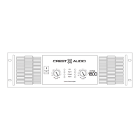
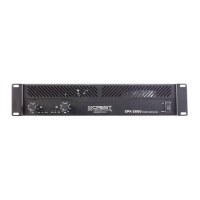
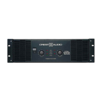
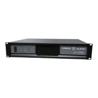
Illustrates the front panel of the CPA1200 and CPA1800 models, detailing controls and indicators.
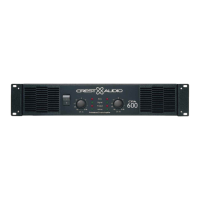
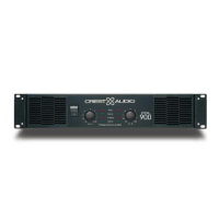
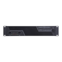
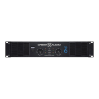
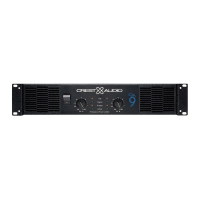
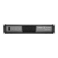
Illustrates the front panel of the CPA400, CPA600, and CPA900 models, detailing controls and indicators.
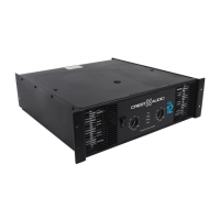
Depicts the rear panel with binding post output connectors for various CPA models.
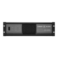
Depicts the rear panel with Speakon output connectors for various CPA models.
Welcome message and overview of Crest Audio's CPA Series amplifiers and their features.
Instructions on how to carefully unpack the amplifier and handle potential shipping damage.
Details on rack-unit size, mounting holes, rear supports, and optional handles for installation.
Description of the front panel mounting ears used for rack installation.
Information on obtaining and using optional rack handles for easier handling.
Explanation of the front panel fan grills for cooling and airflow management.
Details on the front-panel AC power switch and circuit breaker functionality.
Explanation of Signal, Clip, Active, and Protect LEDs and their functions.
Description of the input attenuators for precise gain setting and their adjustment.
Details on the 5-way binding post and Speakon output connectors for amplifier output connections.
Description of the rear panel switch for selecting Stereo, Parallel, or Bridged Mono modes.
Explanation of the ground lift switch for managing signal ground connections and preventing loops.
Details on the rear panel balanced 1/4" TRS and XLR input connectors and their polarity.
Information about the rear panel fan inlet ports and filters for cooling and dust prevention.
Explanation of input XLR polarity configuration and potential changes.
Details on the standard input sensitivity of the CPA Series amplifiers.
Guidelines for connecting power and ensuring appropriate circuit breaker and mains voltage.
Explanation of the amplifier's cooling system, fan operation, and ventilation requirements.
Guidance on using the rear panel XLR or 1/4-inch input connectors for audio signals.
Instructions for connecting speakers using binding posts or Speakon connectors.
Description of Stereo Mode operation, independent channels, and load impedance.
Explanation of Parallel Mode, where Channel A input drives both outputs.
Details on Bridged Mono Mode, combining channels for higher power, and precautions.
Diagrams showing speaker connections for Stereo Mode using binding posts.
Diagrams showing speaker connections for Parallel Mode using binding posts.
Diagrams showing speaker connections for Bridged Mono Mode using binding posts.
Diagrams showing speaker connections for Stereo Mode using Speakon connectors.
Diagrams showing speaker connections for Parallel Mode using Speakon connectors.
Diagrams showing speaker connections for Bridged Mono Mode using Speakon connectors.
Explanation of Active Clip Limiting (ACL) to protect speakers from clipping.
Details on Instantaneous Gain Modulation (IGM) for safe operation with difficult loads.
Explanation of the AutoRamp feature that gradually increases gain on power-up.
Description of thermal protection circuits that safeguard against overheating.
Explanation of short circuit protection mechanisms to protect the amplifier and speakers.
Details on DC voltage detection and protection to prevent speaker damage.
Explanation of high-pass filtering and relay protection against excessive subsonic frequencies.
Precautions for speaker protection, including power limits, clipping, and crossover usage.
Guidance on selecting appropriate wire gauge for speaker cables to minimize power loss.
Instructions for maintenance, focusing on cleaning fan filters and user-serviceable parts.
Highlights the user's responsibility for proper installation, wiring, and operation of the amplifier.
Information on obtaining service, contacting Crest Audio, and procedures for repairs.
| Type | Power Amplifier |
|---|---|
| Channels | 2 |
| Input Impedance | 20 kOhms balanced, 10 kOhms unbalanced |
| Frequency Response | 20Hz - 20kHz, +0/-0.5dB |
| Power (4 ohms, stereo) | 1000W |
| Power (8 ohms, stereo) | 600W |
| THD | <0.03% |
| S/N Ratio | >100dB |
| Total Harmonic Distortion | <0.03% |