3.1.3 Alignment procedure:
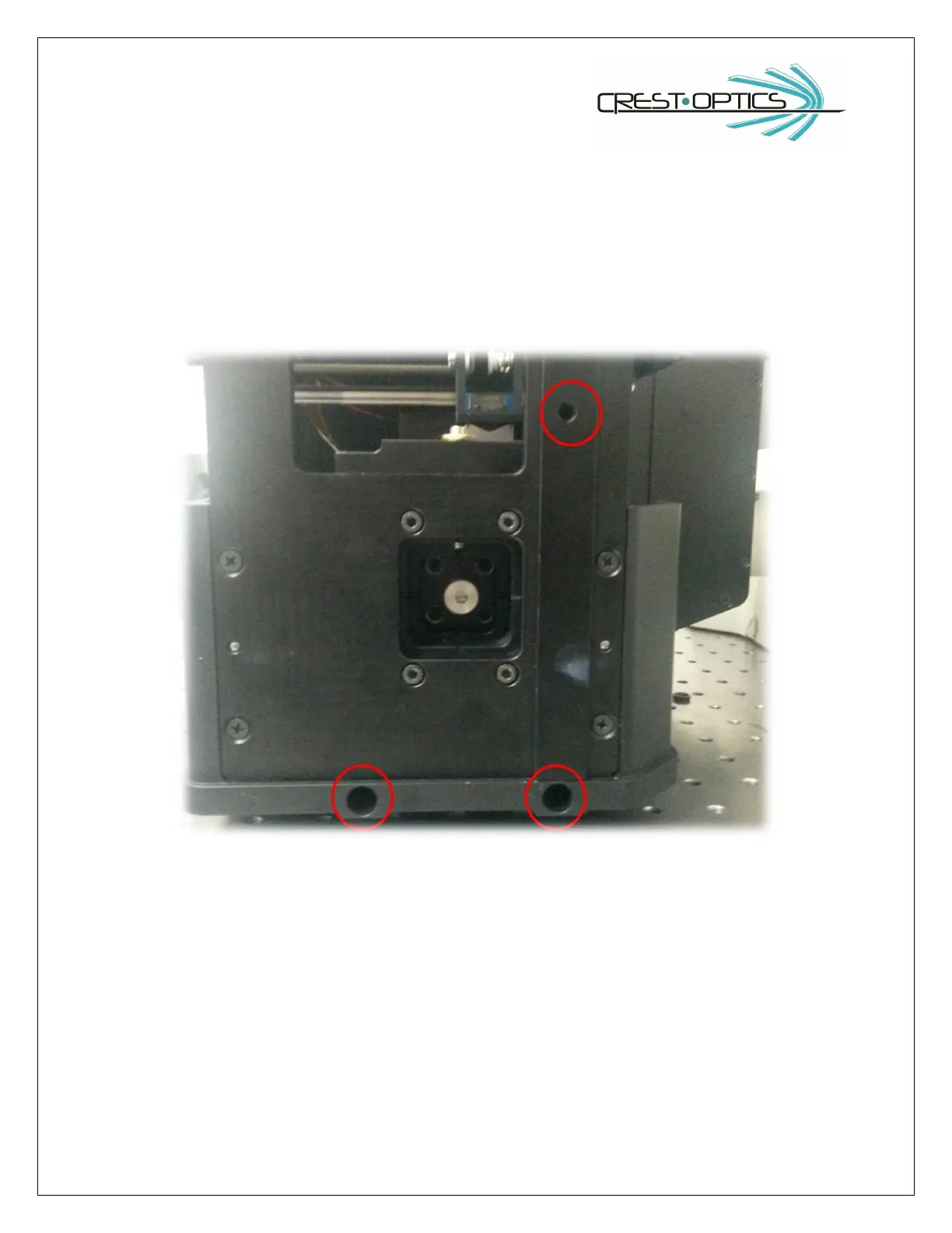
VCS module has three hexagonal captive screws that allow the connection to the X-light V2. Screws are
already mounted inside the module (see picture below)
VCS module is also provided with two pins. During the VCS module connection, before screwing, be sure to insert the
pins in the corresponding holes on the X-light V2 side (see below).