CRESTRON
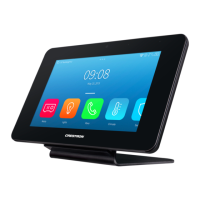
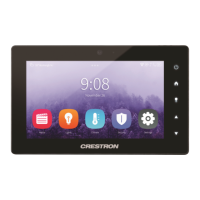
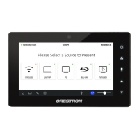
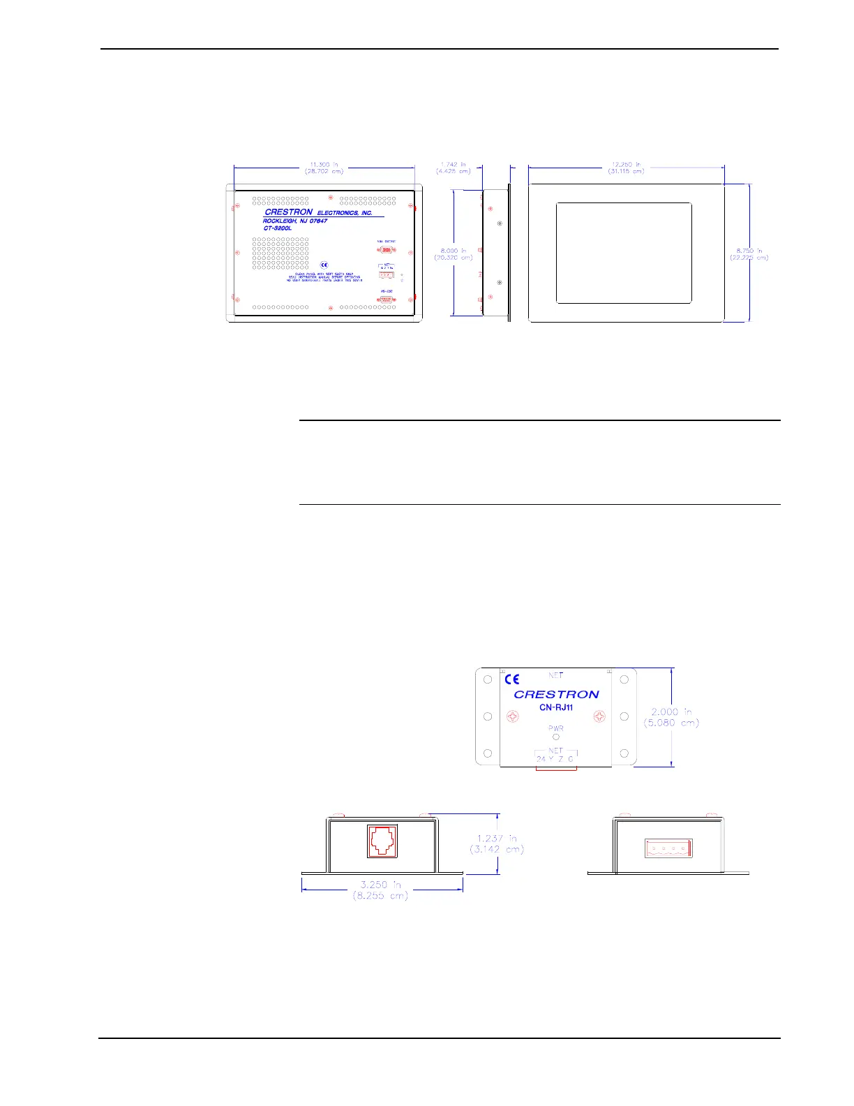
four-pin network, and nine-pin RS-232 connector ports are located on the rear of the
panel.
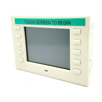
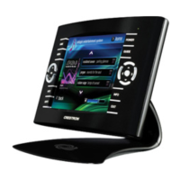
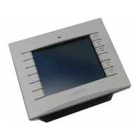
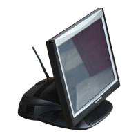
Physical Views of Lectern Series 3200 Touchpanel
BACK VIEW SIDE VIEW FRONT VIEW
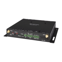
Interface Module: CN-RJ11
NOTE: The tiltcase Series 3200 touchpanel is supplied with a cable assembly that
connects to the CN-RJ11 (supplied). Pinout information is provided on the next
page. If the assembly must be modified in any way, Crestron cannot guarantee the
behavior of the touchpanel. The product may not function accordingly, as stated in
this Operations Guide.
Crestron’s CN-RJ11 is a network one-to-one converter that interfaces four-wire
Cresnet and modular devices. The converter is housed in a black enclosure with silk-
screened top panel, shown after this paragraph. A four-pin network connector is
located on one side of the unit. A six-position, RJ11 modular telephone jack is
located on the opposite side. At the shorter sides of the CN-RJ11, the enclosure
extends to form feet at a right angle to the side. There are three holes per foot for
inserting screws to further stabilize the unit.
Physical Views of the CN-RJ11
SIDE VIEW (RJ11 CONNECTOR)
TOP VIEW
SIDE VIEW (4-PIN CONNECTOR)
4 • Series 3200 Touchpanels Operations Guide - DOC. 5725
 Loading...