Crestron CEN-HPRFGW High Powered RF Gateway
Connectors, Controls & Indicators
# CONNECTORS
1
,
CONTROLS &
INDICATORS
DESCRIPTION
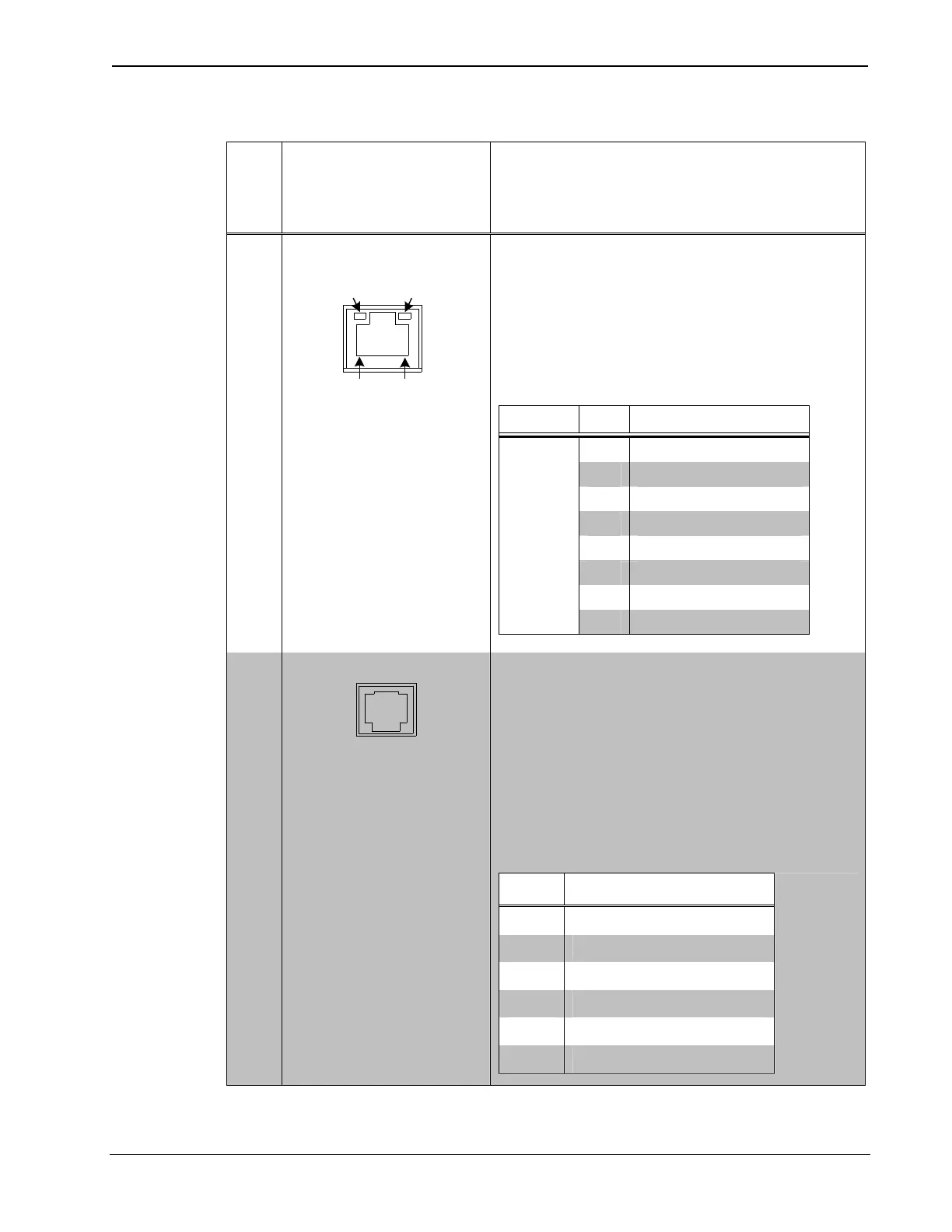
1 LAN
2
GREEN
LED
YELLOW
LED
PIN 8
PIN 1
(1) 8-wire RJ-45 with two LED
indicators;
10/100BASE-T Ethernet port;
Green LED indicates link status;
Yellow LED indicates Ethernet
activity
TYPE PIN SIGNALS
1 TD+
2 TD-
3 RD+
4 Connected to pin 5
5 Connected to pin 4
6 RD-
7 Connected to pin 8
8-
Position
RJ-45
8 Connected to pin 7
2 COMPUTER
3
(1) 6-pin RJ-11 female, computer
console port;
Bidirectional RS-232 up to 115.2 k
baud;
Hardware and software
handshaking support;
2 ft (0.6 m) RJ-11 to DB9F adapter
cable included
PIN DESCRIPTION
1 CTS
2 GND
3 RXD
4 TXD
5 RTS
6 N/C (Not connected)
(Continued on following page)
Operations & Installation Guide – DOC. 6587B High Powered Gateway: CEN-HPRFGW • 7
 Loading...