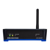
High Powered RF Gateway Crestron CEN-HPRFGW
Connectors, Controls & Indicators (Continued)
# CONNECTORS
1
,
CONTROLS &
INDICATORS
DESCRIPTION
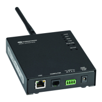
3 NET
4
(1) 3.5 mm detachable terminal
block;
Cresnet slave port, connects to
Cresnet control network
Pin 1 (24) Power
(24 Volts DC)
Pin 2 (Y) Data
Pin 3 (Z) Data
Pin 4 (G) Ground
4 PWR
12 VDC 0.5A
4
(1) 2.5 mm barrel DC power jack,
12 Volt DC power input
(power supply included
5
)
5 PWR LED (1) Green LED, indicates DC power
supplied from Cresnet network or
12 Volt DC input
6 NET LED (1) Yellow LED, indicates
communication with the Cresnet
system
7 RXD LED (1) Red LED, indicates data is
being received from wireless
network devices
8 TXD LED (1) Red LED, indicates data is
being transmitted to wireless
network devices
9 ACQUIRE
(Button and LED)
(1) Recessed pushbutton with red
LED, used to configure the wireless
network
10 SETUP
(Button and LED)
(1) Recessed pushbutton with red
LED, used for touch-settable ID
(TSID) and Ethernet auto-discovery
11 ANTENNA For (included) antenna
1. Interface connector for NET port is provided with the unit.
8 • High Powered Gateway: CEN-HPRFGW Operations & Installation Guide – DOC. 6587B
 Loading...