Crestron CP2/CP2E 2-Series Integrated Control Processor
Physical Description
The CP2/CP2E integrated control systems are housed in black enclosures with
labeling on the front and rear panels. The front panels of both units include standard
LEDs and two reset buttons. All connections to the units are made through their rear
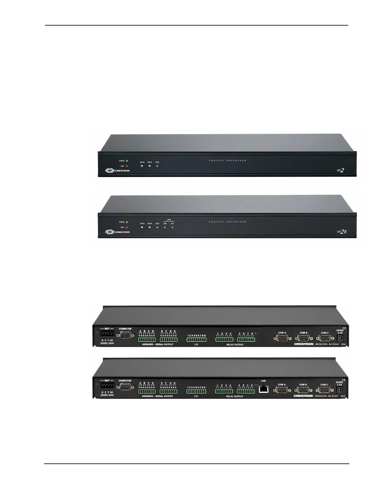
panels. The front panels of the CP2 and CP2E are shown below.
Front and Rear Panels
The front panels of the CP2 and CP2E are shown below.
CP2/CP2E Front Panels
The rear panels of the units are shown below. Both units contain a single RS-232
computer port, a network connector, three COM ports, eight one-way IR/serial ports,
eight I/O ports, eight relay ports, and a 24VDC male receptacle for power supplied
through an AC power pack (purchased separately). The CP2E also contains a single
Ethernet port.
CP2/CP2E Rear Panels
Rubber feet are supplied and can be attached to the base of the unit for stability and
to prevent slippage in shelf placement and stacking configurations. The unit may also
be rack mounted by attaching the supplied metal flanges (ears).
Operations Guide - DOC. 5980 2-Series Integrated Control Processor: CP2/CP2E• 3