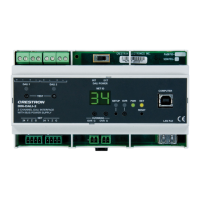
Crestron DIN-DALI-2 DIN Rail 2 Channel DALI Interface
Programming Guide – DOC. 7365A DIN Rail 2 Channel DALI Interface: DIN-DALI-2
5
c. Verify the new ballast can be controlled using the TEST button for the
applicable loop. Tapping the TEST button toggles the state of all
ballasts connected to that loop.
d. If the ballast does not respond, check the DALI wiring. Wiring must
work properly before replacement process continues.
2. Initiate device discovery and replacement process.
a. Press and hold the ID Up and ID Down buttons until the display
shows br, which takes approximately 5 seconds.
b. Within 10 seconds of entering this mode, tap the TEST button for the
loop to which the new ballast is connected. The display blinks br
during the device discovery process. This may take a few minutes to
complete.
c. When discovery is complete, the display shows the address (in hex) of
the missing ballast (00 – 3F) and the new ballast starts flashing.
d. Press and hold the applicable TEST button for 3 seconds to initiate
reprogramming of the new ballast.
e. Once the new ballast has been programmed, the DIN-DALI-2 returns to
normal operation and displays its Cresnet ID.
Replacing Multiple Ballasts
To replace multiple ballasts, perform the following procedure for each affected loop.
1. Test wiring.
a. Replace all failed ballasts.
b. Tap the TEST 1 and TEST 2 buttons to toggle the state of all ballasts
connected and verify the new ballasts respond.
c. If a ballast does not respond, check the DALI wiring. Wiring must
work properly before replacement process continues.
2. Initiate device discovery and replacement process.
a. Press and hold the ID Up and ID Down buttons until the display shows
br, which takes approximately 5 seconds.
b. Within 10 seconds of entering this mode, tap the TEST 1 button (for
loop 1) or the TEST 2 button (for loop 2). The display blinks br during
the device discovery process This may take a few minutes to complete.
c. When discovery is complete, the first new ballast found on the loop
flashes to indicate that it has been selected for addressing.
d. The display shows the address (in hex) of the first missing ballast
(00 – 3F).
a. Use the ID Up and ID Down buttons to select the address to assign to
the flashing ballast. Refer to floor maps created during initial
commissioning to determine correct address.
e. Press and hold the TEST 1 button (for loop 1) or TEST 2 button (for
loop 2) button for 3 seconds to initiate reprogramming of the selected
ballast. The display switches to show the address (in hex) of the next
missing ballast and the next new ballast begins flashing.
f. Use the ID Up and ID Down buttons to assign an address to the
flashing ballast.