DIN Rail 2 Channel DALI Interface Crestron DIN-DALI-2
16
DIN Rail 2 Channel DALI Interface: DIN-DALI-2 Programming Guide – DOC. 7365A
Appendix A: DALI Protocol Summary
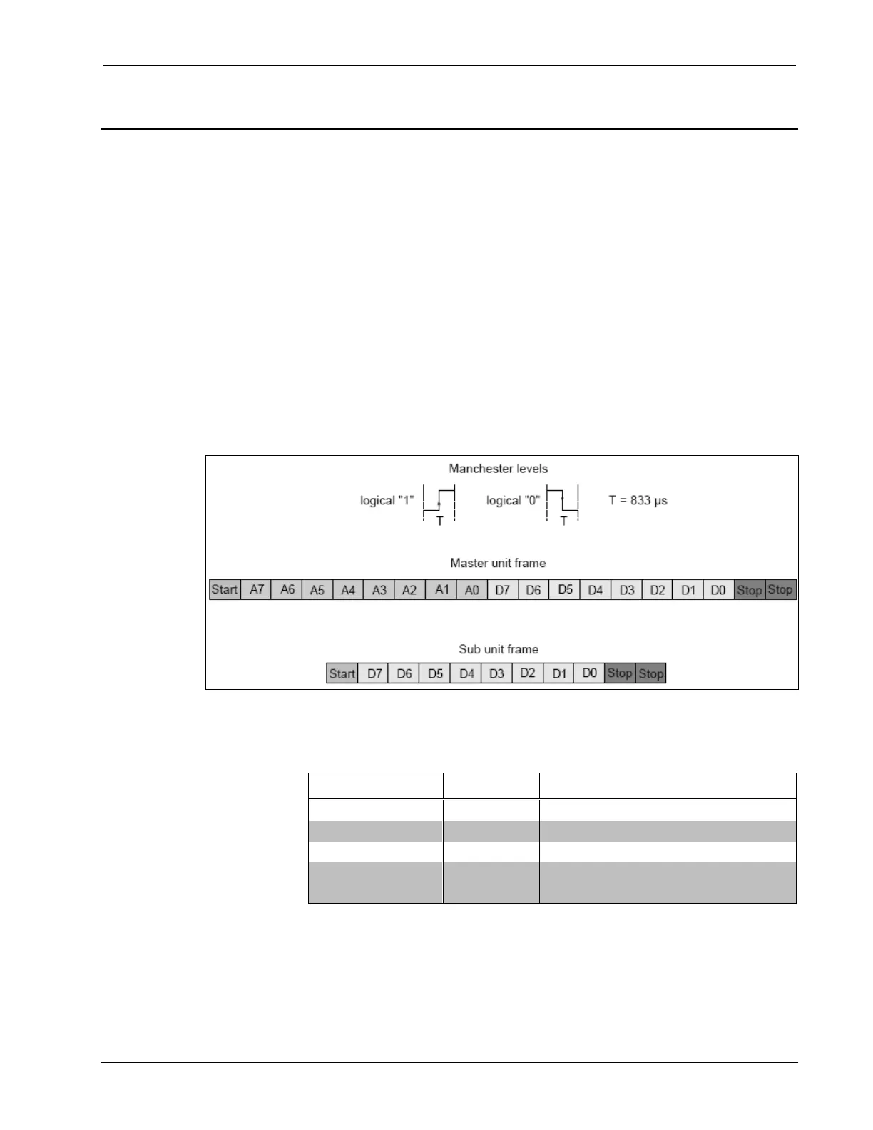
DALI uses a Manchester encoded unidirectional serial protocol with a transmission
rate of 1.2 kHz. The bit time is 833 μs ±10%.
The frame of the main unit consists of 19 bits (15.9 ms):
• 1 start-bit (logical 1)
• 8 address bits
• 8 data bits
• 2 stop bits (physical high level)
The answer frame of the sub unit consists of 11 bits (9.2 ms):
• 1 start-bit (logical 1)
• 8 data bits
• 2 stop bits (physical high level)
DALI Protocol Configuration
To select the devices by the different addressing modes (broadcast, group, single),
use the address types shown in the following table.
Addresses Used for Different Command Types
COMMAND TYPE ADDRESS* NOTES
Broadcast 1111111S
Group 100AAAAS AAAA = 0 to F (Group Address 0-15)
Single 0AAAAAAS AAAAAA = 0 to 3F (Short Address 0-63)
Special command: 101CCCC1;
110CCCC1
CCCC = special command number
* The S distinguishes between a direct arc power command and a DALI command.
If S = 0 the following data is interpreted as a power level with a value between
0x00 (off) and 0xFE (maximum power level).
Standard commands are listed in the table beginning on the following page.