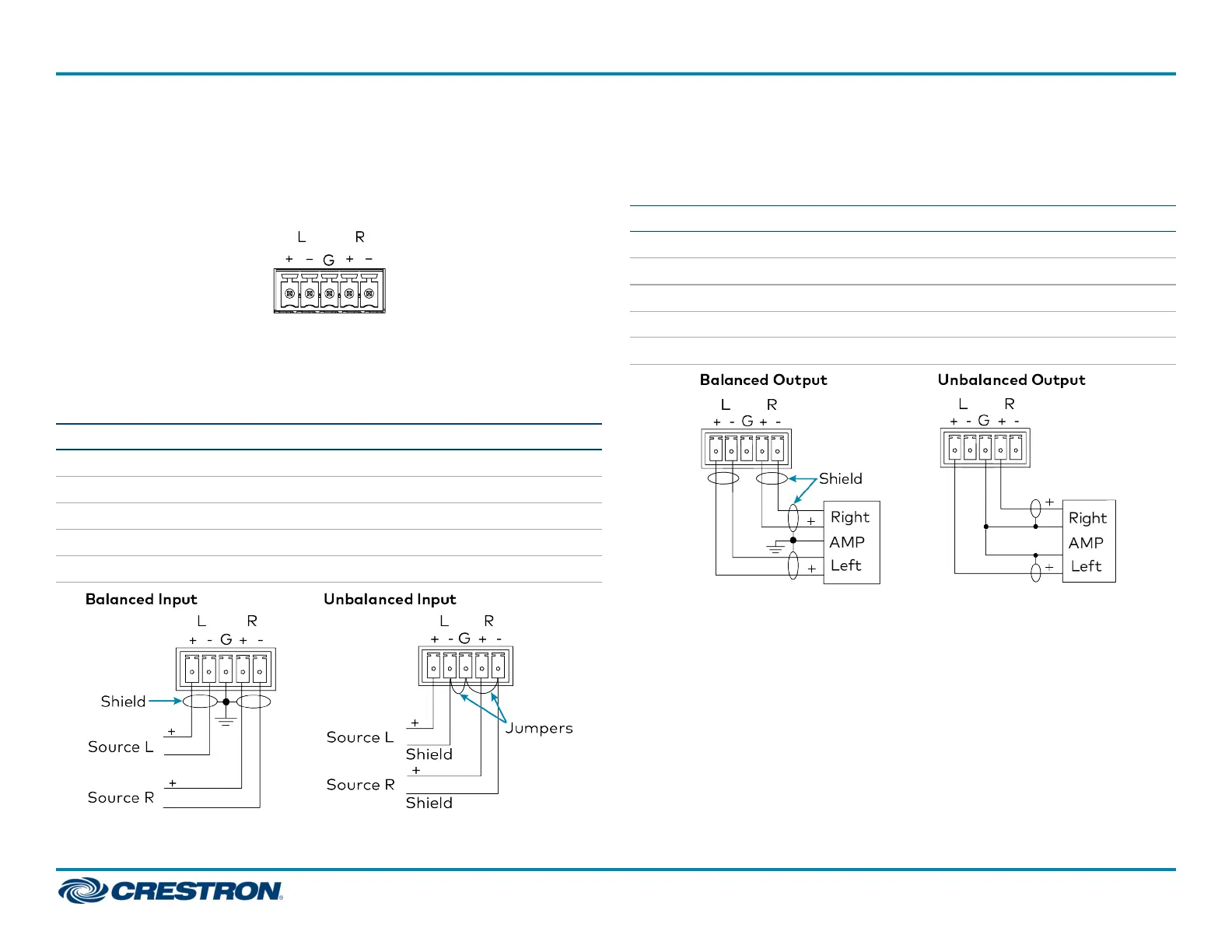
AUDIO I/O Connector Pin Assignments
The AUDIO I/O connector uses a 5-pin terminal block for balanced or
unbalanced analog audio input or output.
AUDIO I/O Connector
Balanced/Unbalanced Audio Input
Refer to the following table and diagrams for analog audio input pin
assignments and connection information.
Signal Name Balanced Audio Input Unbalanced Audio Input
+ L+ L+ In
− L− L− Signal return, jumper to GND
G Shield/ground Ground
+ R+ R+ In
− R− R− Signal return, jumper to GND
Balanced/Unbalanced Audio Output
Refer to the following table and diagrams for analog audio output pin
assignments and connection information.
Signal Name Balanced Audio Output Unbalanced Audio Output
+ L+ L+ Out
− L− Open
G Shield/ground Common ground
+ R+ R+ Out
− R− Open
5
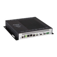
DM-NVX-350C, DM-NVX-351C, and DM-NVX-352C
QuickStart
DM NVX® 4K60 4:4:4 HDR Network AV Encoder/Decoder Cards

 Loading...