Crestron DM-RMC-100-C DigitalMedia 8G+ Receiver 100
Operations & Installation Guide – DOC. 7000C DigitalMedia 8G+ Receiver 100: DM-RMC-100-C 11
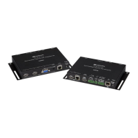
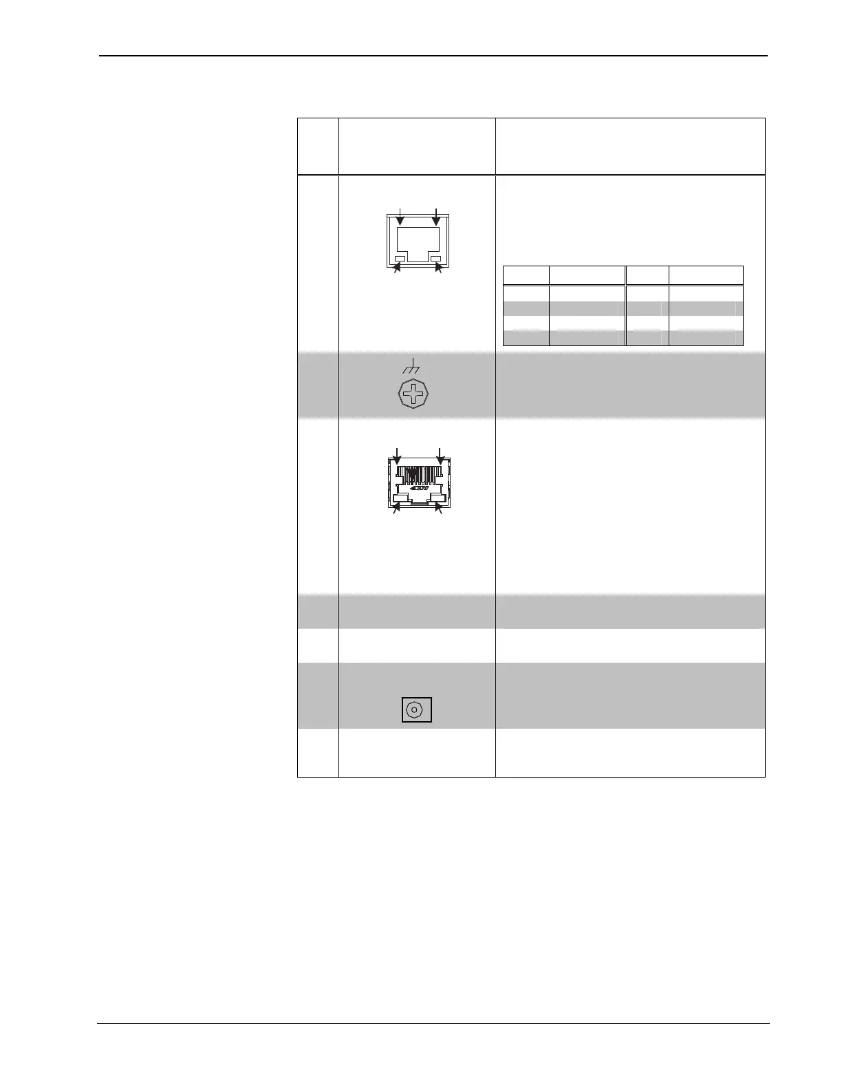
Connectors, Controls & Indicators
#
CONNECTORS
1
,
CONTROLS &
INDICATORS
DESCRIPTION
5
LAN
Green
LED
Amber
LED
Pin 8
Pin 1
(1) 8-pin RJ-45 female, shielded, with two
LED indicators;
10BASE-T/100BASE-TX Ethernet port;
Green LED indicates Ethernet link status;
Amber LED indicates Ethernet activity
PIN SIGNAL PIN SIGNAL
1 TX + 5 N/C
2 TX - 6 RX -
3 RX + 7 N/C
4 N/C 8 N/C
6
(1) 6-32 screw, chassis ground lug
7
DM IN
4
Green
LED
mber
LED
Pin 8
Pin 1
(1) 8-pin RJ-45 female, shielded, with two
LED indicators;
DM 8G+ input, HDBaseT compliant;
PoDM and PoH PD (Powered Device) port
5
;
Connects to the DM 8G+ output of a DM
switcher, transmitter, or other DM device, or
to an HDBaseT device via CAT5e or
Crestron DM-CBL-8G cable
6
;
Green LED indicates DM link status;
Solid amber LED indicates HDCP video;
Blinking amber LED indicates non-HDCP
video
8 RESET
(1) Miniature recessed push button for
hardware reset
9
SETUP
(Button and LED)
(1) Miniature recessed push button for
Ethernet setup and (1) red LED
10
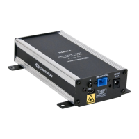
24 V
0.75A MAX
(1) 2.1 x 5.5 mm dc power connector;
24 volt dc power input;
Power pack included
11 Power LED
(1) Green LED, indicates operating power
supplied from local power pack, PoDM, or
PoH
1. Interface connectors for the COM and IR ports are provided with the unit.
2. HDMI requires an appropriate adapter or interface cable to accommodate a DVI signal. CBL-HD-DVI
interface cable sold separately.
3. Maximum string length for serial commands sent via the IR port should be no greater than
40 characters.
 Loading...