DO GUIDE
DOC. 7743C (2044941) 05.16
Specications subject to change without notice.
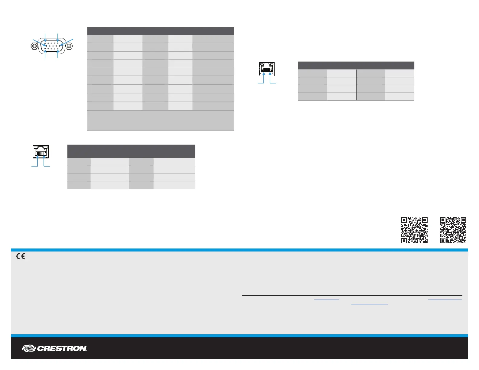
VGA IN Connector Pin Assignments (DM-TX-4K-302-C Only)
DM OUT Connector Wiring
NOTE: The DM OUT port of the DM-TX-4K-302-C is a PoDM+ (Power over DM) PD (Powered
Device) port. The DM OUT port of the DM-TX-4K-202-C is a standard PoDM PD port. To
receive PoDM+ or PoDM, the device requires connection to a DigitalMedia™ switcher or other
equipment that has a corresponding PoDM+ or PoDM PSE (Power Sourcing Equipment) port.
Any wiring that is connected to a PoDM+ or PoDM PSE port is for intrabuilding use only and
should not be connected to a line that runs outside of the building in which the PSE is located.
Connection to the included power pack is not required when PoDM+ or PoDM is used to power
the device.
NOTE: To enable the supply of power to an external USB device via the USB HID port,
the DM-TX-4K-302-C must be powered using the included power pack or PoDM+.
The DM-TX-4K-302-C may be powered using standard PoDM if no USB device is connected
to the USB HID port.
LAN Connector Pin Assignments
DO Set the IP Address
The conguration of the transmitter within the DigitalMedia 8G+
®
system determines how the IP
address of the transmitter is set:
• If the transmitter connects to a DigitalMedia switcher, the transmitter is congured by the
switcher automatically.
• If the transmitter connects to a DigitalMedia 8G+ receiver, the transmitter uses its own
conguration settings. By default, DHCP (Dynamic Host Conguration Protocol) is enabled.
If assignment of the default IP address to the transmitter is desired, hold down the SETUP
button while the unit boots up. The default IP address overwrites the current setting.
The default IP address of the DM-TX-4K-202-C and the DM-TX-4K-302-C is 192.168.1.205.
To manually set a different IP address, use the Crestron Toolbox™ application.
DO Learn More
Visit the website for additional information and the latest
rmware updates. To learn more about this product, use a
QR reader application on your mobile device to scan the
QR images.
Crestron Electronics
15 Volvo Drive, Rockleigh, NJ 07647
888.CRESTRON | www.crestron.com
As of the date of manufacture, the product has been tested and found to comply with specications for CE marking.
Federal Communications Commission (FCC) Compliance Statement
This device complies with part 15 of the FCC Rules. Operation is subject to the following two conditions:
(1) This device may not cause harmful interference, and (2) this device must accept any interference received, including interference
that may cause undesired operation.
CAUTION: Changes or modications not expressly approved by the manufacturer responsible for compliance could void the
user’s authority to operate the equipment.
NOTE: This equipment has been tested and found to comply with the limits for a Class B digital device, pursuant to part 15 of the
FCC Rules. These limits are designed to provide reasonable protection against harmful interference in a residential installation.
This equipment generates, uses and can radiate radio frequency energy and, if not installed and used in accordance with the
instructions, may cause harmful interference to radio communications. However, there is no guarantee that interference will not
occur in a particular installation.
If this equipment does cause harmful interference to radio or television reception, which can be determined by turning the
equipment off and on, the user is encouraged to try to correct the interference by one or more of the following measures:
• Reorient or relocate the receiving antenna.
• Increase the separation between the equipment and receiver.
• Connect the equipment into an outlet on a circuit different from that to which the receiver is connected.
• Consult the dealer or an experienced radio/TV technician for help.
Industry Canada (IC) Compliance Statement
CAN ICES-3(B)/NMB-3(B)
The specic patents that cover Crestron products are listed at patents.crestron.com. The product warranty can be found at www.crestron.com/warranty.
Certain Crestron products contain open source software. For specic information, please visit www.crestron.com/opensource.
Crestron, the Crestron logo, Crestron Toolbox, DigitalMedia, DigitalMedia 8G+, and DM are either trademarks or registered trademarks of Crestron Electronics, Inc. in the United States and/
or other countries. HDBaseT and the HDBaseT Alliance logo are either trademarks or registered trademarks of the HDBaseT Alliance in the United States and/or other countries. HDMI and the
HDMI logo are either trademarks or registered trademarks of HDMI Licensing LLC in the United States and/or other countries. Other trademarks, registered trademarks, and trade names may
be used in this document to refer to either the entities claiming the marks and names or their products. Crestron disclaims any proprietary interest in the marks and names of others. Crestron
is not responsible for errors in typography or photography.
This document was written by the Technical Publications department at Crestron.
©2016 Crestron Electronics, Inc.
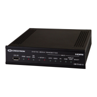
DM-TX-4K-202-C
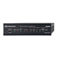
DM-TX-4K-302-C
PIN
NUM.
WIRE COLOR
PIN
NUM.
WIRE COLOR
1 Orange/White 5 Blue/White
2 Orange 6 Green
3 Green/White 7 Brown/White
4 Blue 8 Brown
PIN NUM. SIGNAL PIN NUM. SIGNAL
1 TX+ 5 N/C
2 TX- 6 RX-
3 RX+ 7 N/C
4 N/C 8 N/C
PIN NUM. RGB YPbPr S-VIDEO COMPOSITE
1 R Pr C
2 G Y Y
3 B Pb COMP
5 GND GND GND GND
6 RED_GND Pr_GND C_GND
7 GRN_GND Y_GND Y_GND
8 BLU_GND Pb_GND
13 H
14 V
NOTE: For best video performance, ground connections should
be kept separate. Do not connect ground wires to the connector
shell. The connector shell is reserved for the cable shield.
Pin 10
Pin 5 Pin 1
Pin 6
Pin 15 Pin 11
5
1
11
15

 Loading...