DO GUIDE
DOC. 7654A (2042246) 10.14
Speci cations subject to change without notice.
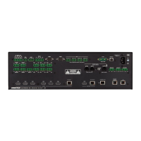
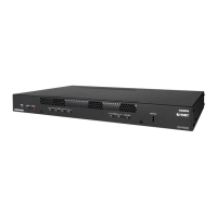
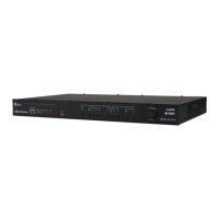
Making Connections to the Rear Panel
Make connections to the rear panel as follows:
VGA IN 1–4: Connect to RGB (VGA), component, S-video, or
composite video sources (VGA cables not included).
AUDIO IN 1–4: Connect to unbalanced audio sources
(unbalanced 3.5 mm TRS mini phone jack cables not included).
HDMI IN 1–4: Connect to HDMI
®
audio/video sources (HDMI
cables not included).
DM IN 1–2: Connect to the DM 8G+™ output of DigitalMedia™
transmitters or other DigitalMedia devices or to third-party
HDBaseT
®
devices (Crestron
®
DM-CBL-ULTRA, DM-CBL-8G,
DM-CBL, DM-CBL-D, or third-party CAT5e [or better] UTP or STP
cables not included).*
HDMI OUT: Connect to the receiving device (HDMI cable not
included).
DM OUT: Connect to the DM 8G+ input of a DigitalMedia receiver
or other DigitalMedia device or to a third-party HDBaseT device
(Crestron DM-CBL-ULTRA, DM-CBL-8G, DM-CBL, DM-CBL-D, or
third-party CAT5e [or better] UTP or STP cable not included).*
RELAY 1–2: Connect to controllable devices (cables not
included).
INPUT: Connect to a digital input, digital output, or analog output
device (cable not included).
AUDIO OUT: Connect to the receiving device using the supplied
5-pin interface connector (cable not included).
IR OUT: Connect to the included Crestron STIRP IR emitter
probe.
MIC IN: Connect to a microphone.
COM: Connect to the device to be controlled using the included
5-pin interface connector (RS-232 data communications cable
not included).
LAN: Connect to the local area network (Ethernet cable not
included).
USB 1–4 (Type A): Connect to the USB port of TT-100 Series
presentation interfaces (USB cable included with presentation
interfaces).
G: Connect to earth ground (building steel).
NET: Connect to the 4-pin NET port of a Cresnet
®
device using
the included 4-pin interface connector (Cresnet control cable not
included).
100–240V~1.4A 50/60 Hz: Connect to a 120 V power outlet using the
included power cord.
DO Allow DHCP Mode or Set a Static IP Address
DHCP is enabled by default. Via the USB connection between the
COMPUTER port of the DMPS3-4K-150-C and a PC running Crestron
Toolbox™, use the Device Discovery Tool in Crestron Toolbox to nd the IP
address of the DMPS3-4K-150-C. If desired, set a static IP address using
Crestron Toolbox or the web-based con guration interface of the
DMPS3-4K-150-C.
DO Commission the DMPS3-4K-150-C System
Using the web-based con guration interface, commission the
DMPS3-4K-150-C system by con guring EDID, audio, video, and
DigitalMedia endpoints. In addition, use the web-based con guration
interface to update rmware.
DO Allow Automatic Switching or
Manually Select an Input
By default, automatic switching of inputs is enabled. Automatic switching
causes the last connected input to be routed to the output. The AUTO LED
lights to indicate that automatic switching is enabled.
To manually select and activate the desired input, press one of the VGA
(1–4), HDMI (1–4), or DM (1–2) INPUT SELECT buttons. Refer to the
following table for a summary of the LED behavior of selected and
nonselected inputs.
NOTE: Manual selection of an input disables automatic switching. When
automatic switching is disabled, the AUTO LED goes off.
DO Use the Built-In Control Program
The DMPS3-4K-150-C provides a built-in program that enables complete
system control without requiring additional programming. Control is
accomplished using the Crestron TSW-750-B PAK 7” tabletop touch
screen, the Crestron XPanel interface, or the Apple
®
iPad
®
app. Refer to the
operations guide (Doc. 7646) at www.crestron.com/manuals for additional
information about the built-in control program.
As of the date of manufacture, the product has been tested and found to comply with speci cations for CE marking.
Federal Communications Commission (FCC) Compliance Statement
This device complies with part 15 of the FCC Rules. Operation is subject to the following conditions:
(1) This device may not cause harmful interference and (2) this device must accept any interference received, including interference that may cause undesired operation.
Caution: Changes or modi cations not expressly approved by the manufacturer responsible for compliance could void the user’s authority to operate the equipment.
Note: This equipment has been tested and found to comply with the limits for a Class B digital device, pursuant to part 15 of the FCC Rules. These limits are designed to provide reasonable protection against harmful interference in a residential
installation. This equipment generates, uses and can radiate radio frequency energy and, if not installed and used in accordance with the instructions, may cause harmful interference to radio communications. However, there is no guarantee that
interference will not occur in a particular installation.
If this equipment does cause harmful interference to radio or television reception, which can be determined by turning the equipment off and on, the user is encouraged to try to correct the interference by one or more of the following measures:
• Reorient or relocate the receiving antenna
• Increase the separation between the equipment and receiver
• Connect the equipment into an outlet on a circuit different from that to which the receiver is connected
• Consult the dealer or an experienced radio/TV technician for help
Industry Canada (IC) Compliance Statement
CAN ICES-3(B)/NMB-3(B)
The speci c patents that cover Crestron products are listed at www.patents.crestron.com. Product warranty can be found at www.crestron.com/warranty.
Crestron, the Crestron logo, 3-Series, Cresnet, Crestron Toolbox, DigitalMedia, and DM 8G+ are either trademarks or registered trademarks of Crestron Electronics, Inc., in the United States and/or other countries. Apple and iPad are either trademarks or registered trademarks of Apple Inc. in the United States
and/or other countries. HDBaseT and the HDBaseT Alliance logo are either trademarks or registered trademarks of the HDBaseT Alliance in the United States and/or other countries. HDMI and the HDMI logo are either trademarks or registered trademarks of HDMI Licensing LLC in the United States and/or other
countries. Other trademarks, registered trademarks, and trade names may be used in this document to refer to either the entities claiming the marks and names or their products. Crestron disclaims any proprietary interest in the marks and names of others. Crestron is not responsible for errors in typography
or photography.
This document was written by the Technical Publications department at Crestron.
©2014 Crestron Electronics, Inc.
DO Learn More
Check the website for the latest rmware updates.
Crestron Electronics 15 Volvo Drive, Rockleigh, NJ 07647
888.CRESTRON | www.crestron.com
* For all resolutions up to UHD and 4K, the maximum cable length is 330 feet (100 meters)
using DM-CBL-ULTRA cable. For resolutions up to 1080p60, UXGA, WUXGA, and 2K DCI, the
maximum cable length is 330 feet (100 meters) using DM-CBL-8G, DM-CBL, DM-CBL-D,
or third-party CAT5e [or better] cable. For higher resolutions up to 4K DCI and UHD, the
maximum cable length is 230 feet (70 meters) using DM-CBL-8G cable or 165 feet (50
meters) using DM-CBL, DM-CBL-D, or CAT5e cable. Shielded cable and connectors are
recommended to safeguard against unpredictable environmental electrical noise that may
impact performance at resolutions above 1080p.
AUDIO IN
VIDEO IN
LAN
L
R
C
O
M
HDMI IN
DM OUT
DISPLAYPORT
VID
IR
S G
24V 0.75A
PC
G
TX
RX
RS
CS
G
CLASS 1
LASER
PRODUCT
DM-TX-401-C
LAPTOP
DM-RMC-100-C
COM
HDMI OUT
GND
TX
RX
RTS
CTS
S
G
S
S
1
2
IR
LAN
DM IN
RESET
SETUP
24 V
0.75A MAX
DM-RMC-100-C
DM ROOM CONTROLLER
PROJECTOR
STEREO
SPEAKERS
LAPTOP
MONITOR
TT-100
TT-100
TT-100
TT-100
AMPLIFIER
DM-TX-201-C
USB HID HDMI RGB AUDIO SETUP
DM - TX - 2 01 - C
DM CO M P UT E R C E NT E R
RESET
IN
LAN DM OUT
HDMI OUT
PWR
24 VDC
0.75A
COMPUTER
LAPTOP
MICROPHONE
TSW-750
PROJECTION
SCREEN
LAN
2
3
4
Color Description
Solid green
The input is the active selection, and an incoming signal
is detected.
Flashing green
The input is the active selection, and an incoming signal is
not detected.
Solid amber
The input is not the active selection, and an incoming
signal is detected.
Off
The input is not the active selection, and an incoming
signal is not detected.
 Loading...