DO GUIDE
Connecting the DMPS3-4K-350-C
DO Determine the Address of the Device
The DMPS3-4K-250-C and DMPS3-4K-350-C can be addressed using the hostname of the device. The default hostname is DMPS3-xxxxxxxx, where
xxxxxxxx consists of the last eight characters (excluding punctuation) of the MAC address. For example, if the MAC address is 00:10:7F:08:09:AA:05, the
default host name is DMPS3-0809AA05. The MAC address is labeled on the rear panel of the device.
Alternatively, the DMPS3-4K-250-C and DMPS3-4K-350-C can be addressed using the IP address of the device. By default, DHCP is enabled. To set a static
IP address, use any of the following:
• Crestron Toolbox™ software on a PC that connects to the device via the Ethernet network
NOTE: The Device Discovery Tool can be used to nd the current IP address.
• A USB connection to the COMPUTER port on the front panel of the device
• The front panel LCD display menu
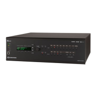
DMPS3-4K-250-C/DMPS3-4K-350-C
3-Series
®
4K DigitalMedia™ Presentations Systems
DO Install the Device
The Crestron
®
DMPS3-4K-250-C and DMPS3-4K-350-C can be mounted into a rack or placed onto a at surface.
Mounting into a Rack
The DMPS3-4K-250-C and DMPS3-4K-350-C each occupy 3U of rack
space. Using a #1 or #2 Phillips screwdriver, attach the two included rack
ears to the device. Then, mount the device into the rack using four mounting
screws (not included).
Placing onto a Flat Surface
When placing the device onto a at surface or stacking it with other
equipment, attach the included feet near the corners on the underside of the
device.
DO Connect the Device
Connect the device as required for the application.
Connecting the DMPS3-4K-250-C
DO Check the Box
QUANTITY PRODUCT COLOR PART NUMBER
2 Bracket, Rack Ear, 3U Black 2033588
1 Cable, USB 2.0, A - B, 6' (1.83 m) 2014966
3 Connector, 2-Pin 2012361
1 Connector, 3-Pin 2003575
4 Connector, 4-Pin 2003576
15 Connector, 5-Pin 2003577
2 Connector, 8-Pin 2003580
4 Foot, 0.5" x 0.5" x 0.23", Rubber Black 2002389
1 Power Cord, 6' 7" (2 m) 2001134
6 Screw, 6-32 x 5/16", Undercut Head, Phillips Black 2007223
Mounting into a Rack
L R L R L R
IR IN:
From
CNXRMIRD
IR receiver
IR - SERIAL OUT 1-4:
To IRP2 IR emitter probe
or one-way serial
controlled devices
RELAY 1-4:
To
controllable
devices
COM A and COM B:
To RS-232 devices
NET:
To Cresnet
®
devices
PoDM+
INPUT PWR:
From Crestron
PoDM+ power
supply
1
100-240V~6.0A
50/60 Hz:
From ac
power outlet
Ground
INPUT 1-4:
From sense output of
digital output devices
(24 volts maximum)
SERVICE:
For factory
use only
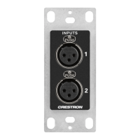
MC/LN 1-6:
From balanced
microphone/
line-level
audio sources
HDMI INPUTS 1-6:
From HDMI
®
audio/video sources
AUD IN 1-5:
From balanced/
unbalanced stereo
line-level analog
audio sources
DM INPUT:
From DM 8G+
®
output of DM
®
transmitter or
other DM
device or from
HDBaseT
®
device
1
HDMI
OUTPUT:
To HDMI
display
DM OUTPUT:
To DM 8G+
input of DM
receiver or
other DM
device or to
HDBaseT
device
1
CONTROL
SUBNET:
To Crestron
local
network
device
1
PROG OUT:
Audio output to
amplier or
amplied speakers
AUX OUT 1-2:
To video
teleconferencing
or codec input
CLASS 2 WIRING:
To 4-ohm/8-ohm
stereo speakers or
70-volt/100-volt
mono speakers
LAN:
10BASE-T/
100BASE-TX/
1000BASE-T
Ethernet to
LAN
CONTENT
LAN:
10BASE-T/
100BASE-TX
Ethernet to
LAN for
AirMedia or
H.264 content
input (optional)
2
L R L R L R
IR IN:
From
CNXRMIRD
IR receiver
IR - SERIAL OUT 1-4:
To IRP2 IR emitter probe
or one-way serial
controlled devices
RELAY 1-4:
To
controllable
devices
COM A and COM B:
To RS-232 devices
NET:
To Cresnet
devices
PoDM+
INPUT PWR:
From Crestron
PoDM+ power
supply
1
100-240V~6.0A
50/60 Hz:
From ac
power outlet
Ground
INPUT 1-4:
From sense output of
digital output devices
(24 volts maximum)
SERVICE:
For factory
use only
SPEAKER OUTPUT
CLASS 2 WIRING:
To 4-ohm/8-ohm
stereo speakers or
70-volt/100-volt
mono speakers
MC/LN 1-6:
From balanced
microphone/
line level
audio sources
HDMI INPUTS 1-6:
From HDMI
audio/video sources
AUD IN 1-5:
From balanced/
unbalanced stereo
line-level analog
audio sources
DM INPUTS:
From DM 8G+
output of DM
transmitter or
other DM
device or from
HDBaseT device
1
HDMI
OUTPUTS:
To HDMI
displays
DM OUTPUTS:
To DM 8G+
input of DM
receiver or
other DM
device or to
HDBaseT
device
1
CONTROL
SUBNET:
To Crestron
local
network
device
1
PROG OUT:
Audio output to
amplier or
amplied speakers
AUX OUT 1-2:
To video
teleconferencing
or codec input
LAN:
10BASE-T/
100BASE-TX/
1000BASE-T
Ethernet to
LAN
CONTENT
LAN:
10BASE-T/
100BASE-TX
Ethernet to
LAN for
AirMedia or
H.264 content
input (optional)
2