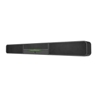
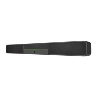
5. Pivot the sound bar away from the wall bracket.
Pivot the Sound Bar
Wall bracket
Sound bar
6. Place the wall bracket over the screws, and hand tighten the screws until the wall bracket is
secured to the wall.
Place and Secure the Wall Bracket
8-AB x 1-1/2” screws (x4)
Wall bracket
Sound bar
7. Route the cables through the cable cutout, and connect the cables as described in
“Hardware Hookup.”
NOTE: The included power cord is typically routed from the wall opening, through the cable
cutout, and to the sound bar.
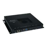
Connect the Device
Make the necessary connections as called out in the following diagram. Connect power last.
Sound Bar, Rear Panel Connections
From AC power outlet
Audio and video to UC-ENGINE
CAMERA
From USB camera
(Pre-connected on UC-SB1-CAM)
AUDIO IN and OUT
Line-level audio input and output
• Connect the included USB cable to the PC port and a USB port on the UC-ENGINE.
• Connect a USB camera (sold separately) to the CAMERA port.
NOTE: On the UC-SB1-CAM, the integrated camera is already connected from the factory.
• Connect the included power cord to the 100-240V~, 0.5A, 50/60Hz power input and an AC
power outlet.
The sound bar also provides unbalanced, stereo analog input and output jacks (AUDIO IN and
OUT, 3.5 mm TRS mini-phone). The input accommodates a line-level audio source, which feeds
to the internal amplifier and speakers with no volume control or other signal processing. The
output can feed an assistive listening system, and carries the same audio signal as the sound bar
speakers.
Complete the Installation
Once all connections are made, pivot the sound bar up to the wall bracket until the sound bar
locks into place.
Operation
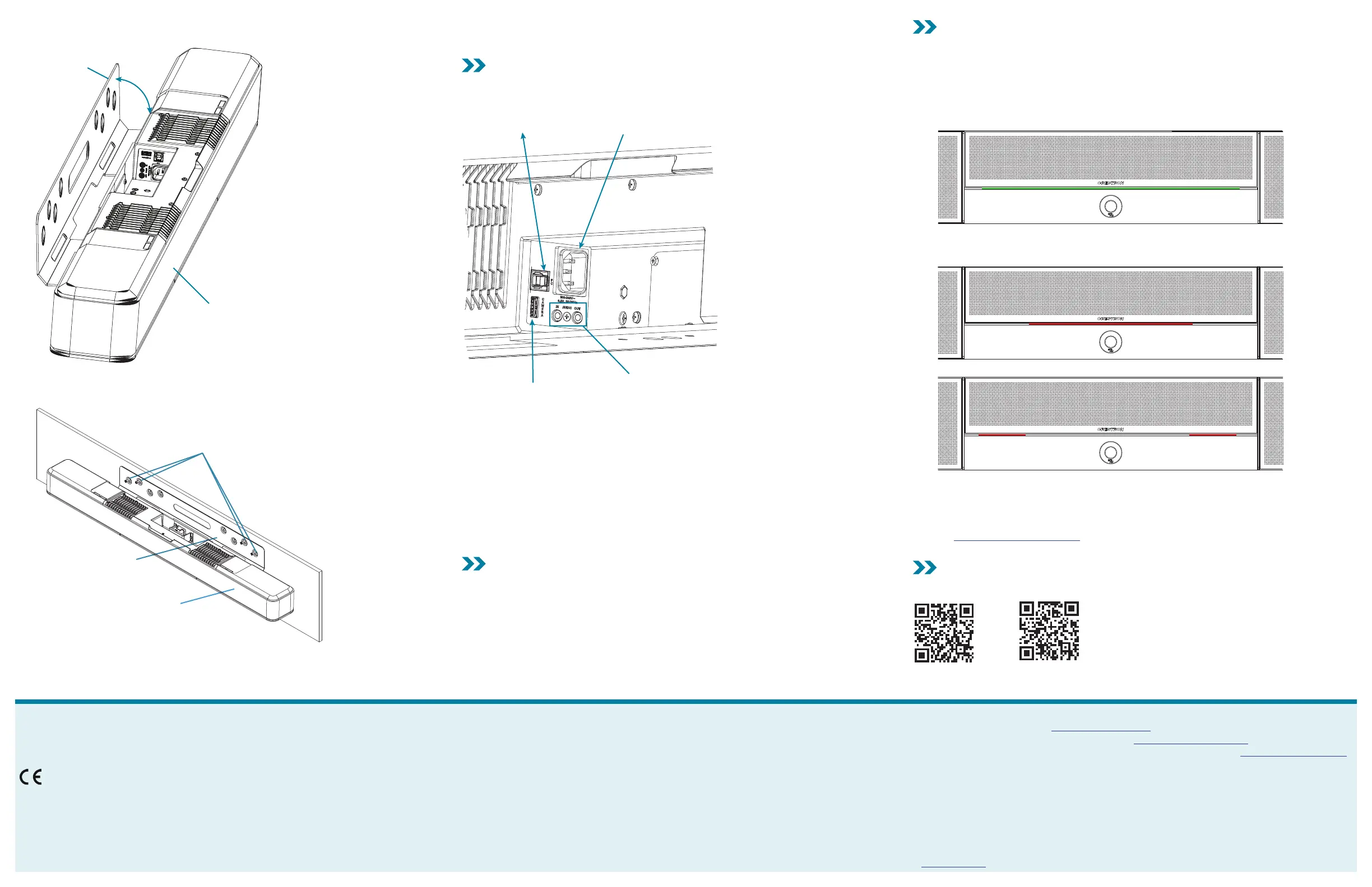
Status
The front panel status bar illuminates to provide operational information.
• A green status bar indicates the volume level. Increasing the volume increases the
illumination. Decreasing the volume decreases the illumination. When the volume = “0”, the
status bar is dark.
• Muting the microphone turns the center of the status bar red. Muting the microphone and
speaker turns the two outer segments of the status bar red.
Microphone and speaker muted
System Control
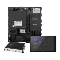
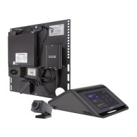
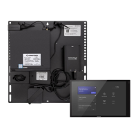
The sound bar can be controlled by a TSW-1060 touch screen that is part of a UC-B160-T Wall
Mount UC Video Conference System for Microsoft Teams® Software. For details, refer to the UC
Video Conference Systems for Microsoft Teams Supplemental Guide Supplemental Guide (Doc.
8360) at www.crestron.com/manuals.
For Additional Information
Scan or click the QR code for detailed product information.
UC-SB1 UC-SB1-CAM
Compliance and Legal
Original Instructions: The U.S. English version of this document is the original instructions. All other languages are a translation
of the original instructions.
Regulatory Model: UC-SB
As of the date of manufacture, the product has been tested and found to comply with specifications for CE marking.
Federal Communications Commission (FCC) Compliance Statement
This device complies with part 15 of the FCC Rules. Operation is subject to the following conditions: (1) This device may not
cause harmful interference and (2) this device must accept any interference received, including interference that may cause
undesired operation.
CAUTION: Changes or modifications not expressly approved by the manufacturer responsible for compliance could void the
user’s authority to operate the equipment.
NOTE: This equipment has been tested and found to comply with the limits for a Class B digital device, pursuant to part 15
of the FCC Rules. These limits are designed to provide reasonable protection against harmful interference in a residential
installation. This equipment generates, uses and can radiate radio frequency energy and, if not installed and used in
accordance with the instructions, may cause harmful interference to radio communications. However, there is no guarantee
that interference will not occur in a particular installation. If this equipment does cause harmful interference to radio or
television reception, which can be determined by turning the equipment off and on, the user is encouraged to try to correct the
interference by one or more of the following measures:
• Reorient or relocate the receiving antenna.
• Increase the separation between the equipment and receiver.
• Connect the equipment into an outlet on a circuit different from that to which the receiver is connected.
• Consult the dealer or an experienced radio/TV technician for help.
Industry Canada (IC) Compliance Statement
CAN ICES-3 (B)/NMB-3(B)
The product warranty can be found at www.crestron.com/warranty.
The specific patents that cover Crestron products are listed at www.crestron.com/legal/patents.
Certain Crestron products contain open source software. For specific information, please visit www.crestron.com/opensource.
Crestron and the Crestron logo are either trademarks or registered trademarks of Crestron Electronics, Inc. in the United
States and/or other countries. Microsoft Teams is either a trademark or registered trademark of Microsoft Corporation in
the United States and/or other countries. Other trademarks, registered trademarks, and trade names may be used in this
document to refer to either the entities claiming the marks and names or their products. Crestron disclaims any proprietary
interest in the marks and names of others. Crestron is not responsible for errors in typography or photography.
©2019 Crestron Electronics, Inc.
Crestron Electronics, Inc.
15 Volvo Drive, Rockleigh, NJ 07647
Tel: 888.CRESTRON
Fax: 201.767.7576
www.crestron.com
Quick Start - Doc. 8417B
(2052941)
01.19
Specifications subject to
change without notice.
 Loading...