EasyManua.ls Logo

CrimeStopper CS-2000.III - User Manual

CrimeStopper CS-2000.III
16 pages
Print Icon
To Next Page IconTo Next Page
Loading...
CS-2000 Series III
REMOTE CONTROL ALARM SYSTEM
INSTALLATION & OPERATING INSTRUCTIONS
INTRODUCTION
CONGRATULATIONS on your choice of an On-Guard Series Remote Alarm System by Crimestopper
Security Products Inc. This booklet contains the information necessary for installing, using, and maintaining
your alarm system. If any questions arise, contact your installation dealer or Crimestopper Security Products
Inc. at the Tech Support number below.
*IMPORTANT INFORMATION: Primary and Optional Features:
-PRIMARY: These are features that must be connected in order for the system to operate properly; i.e. the
Siren, L.E.D., +12V Power, Ground, Doorpin, Override/Program/Valet Button etc.
-OPTIONAL: These are features to be connected if desired or agreed upon by the installing dealer. These
features may also require additional parts and/or labor fees. Consult with your installer beforehand; i.e. Door
Locks, Flashing Lights, Starter disable, Hood/Trunk trigger, and Auxiliary Remote Outputs etc.
TECH SUPPORT
Mon-Fri 8:00 AM-4:30 PM Pacific Time
(800) 998-6880
This device complies with FCC Rules part 15. Operation is subject to the following
two conditions: 1) This device may not cause interference, and (2) this device
must accept any interference that may be received, including interference that may
cause undesired operation. The manufacturer is not responsible for any radio o
r
TV interference caused by unauthorized modification to this equipment. Such
modification could void the user's authority to operate the equipment.
REV. A 11.2003
Question and Answer IconNeed help?

Do you have a question about the CrimeStopper CS-2000.III and is the answer not in the manual?

Summary

Introduction to Crimestopper CS-2000 Series III

Installation Cautions and Warnings

Mounting Instructions

Control Module Mounting Locations

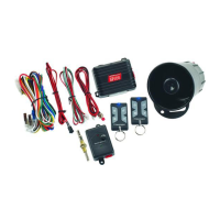
Discusses underdash, driver/passenger side, and under-seat mounting options for the control unit.

Component Mounting Details

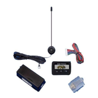
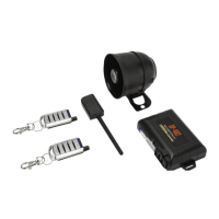
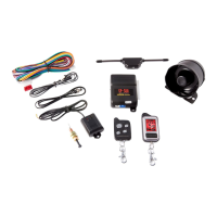
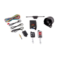
Instructions for mounting the Siren, LED, Shock Sensor, and Valet Button.

Wiring Connections

Door Trigger Wires

Explains connection for negative and positive door trigger inputs (Green & Violet wires).

System Ground & Ignition Power

Covers chassis ground (Black wire) and switched ignition +12V (Yellow wire) connections.

Auxiliary Outputs & Triggers

Details wiring for auxiliary outputs, hood/trunk triggers, and dome light.

Additional Wiring and Connectors

Horn Output & Starter Disable

Wiring for horn pulse/chirp (Brown/White) and negative armed output for starter disable (Orange).

Remote Outputs & Parking Lights

Connects for auxiliary remote outputs (Gray, White/Red) and parking light flashing (White).

Power Input & Pin Plug Functions

Covers +12V power input (Red) and pin plug functions for programming and sensors.

Power Door Lock Wiring Diagrams

Negative;Positive Trigger Door Lock Wiring

Diagrams for connecting to factory negative or positive trigger door locks using 3-pin plug.

Reverse Polarity & Aftermarket Motors

Diagrams for reverse polarity locks and adding aftermarket door lock motors.

Remote Transmitter Programming

Transmitter Programming Procedure

Step-by-step instructions on how to program remote transmitters to the system.

Transmitter Learning Capacity

Notes that the system learns up to 4 transmitters and unlearned ones are dropped.

Option Programming

Programming Options Chart

A chart detailing various programmable features and their settings via transmitter buttons.

Restoring Default Values

Instructions on how to reset all programmable options to their factory default settings.

Option Programming Details

Horn Chirps;Pulses and Passive Arming

Details features controlling horn output and passive (automatic) arming behavior.

Passive Locks & Ignition-Controlled Locks

Configuration for automatic door locking during passive arming and ignition status.

Door Open Warning & Active Re-Arming

Settings for door circuit monitoring delay and automatic re-arming after disarm.

More Option Programming Details

Silent Arm;Disarm & Parking Lights

Features for silent operation confirmation and parking lights on with disarm.

Auxiliary Output & Carjack Protection

Control over trunk pop/aux output and configuration of carjack protection types.

Door Lock Pulse Time

Adjusts the duration of the door lock/unlock pulse for compatibility.

Operating Instructions

Arming, Triggering, and Disarming

Basic operations for arming, what happens during alarm triggering, and disarming the system.

Trunk Pop, Panic, and Shock Sensor

How to use trunk pop, remote panic, and adjust shock sensor sensitivity.

Advanced Operating Modes

Silent Arm;Disarm & Emergency Override

Using Button #2 for silent operation and emergency disarming procedures.

Valet Mode & Intrusion Alerts

How to enter/exit valet mode and interpret prior intrusion alerts.

Zone Bypass & Ignition Door Locks

Handling open zone alerts and ignition-controlled door lock functionality.

Passive Operation Modes

Passive Arming & Dome Light Illumination

Details passive arming countdown and optional dome light illumination upon disarm.

Active Re-Arming & Auxiliary Outputs

Explains fail-safe re-arming and activation of second auxiliary output.

Arm;Disarm with Ignition ON

Allows arming/disarming while the ignition is on, useful for remote start integration.

Carjack Protection

Active Carjack Protection

Procedure for activating and resetting Active Carjack protection.

Passive Carjack Protection

Procedure for activating and resetting Passive Carjack protection.

Full-Time Carjack Protection

Details the full-time carjack protection and its reset requirements.

System Wiring Diagram

CrimeStopper CS-2000.III Specifications

General IconGeneral
BrandCrimeStopper
ModelCS-2000.III
CategoryCar Alarm
LanguageEnglish

Related product manuals