Do you have a question about the CrimeStopper SP-502 and is the answer not in the manual?
Check vehicle manufacturer cautions and warnings regarding electrical service.
Pre-determine locations for control module, buttons, and siren.
Use a volt/ohm meter for testing and locating connections. Avoid test lights.
Identify necessary additional parts like relays or interface modules.
Critical safety and operational warnings for installation and use, including wiring and fuses.
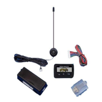
Guidance on mounting key system components like the control module, siren, LED, and sensors.
Connect to body metal using a sheet metal screw and star washer for good ground.
Connects to vehicle parking light circuit for output.
Input source for parking light circuit, can be positive or negative trigger.
Details the purpose and connection for various wires in the 12-pin connector.
Programmable output for trunk pop or auxiliary function.
Activates on second unlock press for separate passenger door unlock.
Connects to starter disable relay to prevent starter grinding during remote start.
Details the purpose and connection for various trigger inputs in the 7-pin connector.
Input for diesel glow plug monitoring or passive carjack trigger.
How to use carjack protection via a toggle or momentary switch.
Diagram showing connection of status LED and Valet/Program/Override button.
Details the function of the 4-pin output connector wires (Blue/Black, Blue/Orange, Violet/White, Green/White).
Sensor installation and adjustment for sensitivity, with LED indicators for warn away and trigger.
Details wire functions and methods for identifying vehicle door lock system types.
Explains requirements for Databus/Canbus systems, needing an interface module.
Wiring diagram for negative trigger door lock systems.
Wiring diagram for positive trigger door lock systems.
Wiring diagram for reverse polarity door lock systems.
Wiring diagram for aftermarket door lock motor installations.
Wiring diagram for separate driver's door unlock with negative trigger systems.
Wiring diagram for separate driver's door unlock with reverse polarity systems.
Notes on when Tachless mode may not operate satisfactorily and alternative modes.
Steps to adjust the voltage reference threshold for fine-tuning Tachless mode.
Explains the three methods of monitoring engine running: Tach Reference, Tachless, and Hybrid.
How to use Tach Reference mode for reliable remote starting via engine speed sensing.
Step-by-step guide for programming the Tach Reference mode.
Explains how the Tach Finder mode assists in locating a Tach source for installation.
Step-by-step instructions for using the Tach Finder mode.
Using Tach Finder mode to simulate cold weather conditions for system testing.
Step-by-step guide to enter and navigate the programmable options menu.
Overview of controlling a second vehicle with the Crimestopper system.
Important notes regarding 2-vehicle programming and remote setup.
List of LED flash codes and their corresponding alarm trigger causes.
List of parking light flash codes and their corresponding remote start error causes.
Wiring requirements and programming for manual transmission installation.
Selection between automatic and manual transmission modes.
Steps for exiting the vehicle safely in manual transmission mode.
Guidance on antenna placement for optimal range and performance.
Diagram of the main control module with labeled connectors.
Information on programming the Data Port Protocol for bypass modules.
Details the purpose and connection for wires in the 6-pin high current connector.
Details wiring for various inputs like switches, sensors, and activation signals.
Details wiring for outputs like LEDs, sirens, relays, and horn.
Details wiring for specific plugs like Door Lock, Low Current, and Starter.
Details the data link cable connection between the bypass module and control module.
Information on programming the correct Data Port Protocol for bypass modules.
| Type | Car Alarm |
|---|---|
| System Type | 2-Way |
| Channels | 4 |
| Number of Buttons on Remotes | 4 |
| Remote Control | Yes |
| Keyless Entry | Yes |
| Remote Start | Yes |
| Panic Mode | Yes |
| Shock Sensor | Yes |
| Starter Kill | Yes |
| LED Status Indicator | Yes |
| Door Trigger | Yes |
| Valet Mode | Yes |
| Remote Range | 1500 ft |
| Compatibility | Most Vehicles |