EasyManua.ls Logo

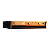
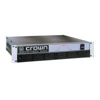
Crown 2400 User Manual

Crown 2400
29 pages
To Next Page IconTo Next Page
Page #1 background imageLoading...
Page #1 background image
Micro-Tech 2400 Amplifier Service Manual
1
MICRO-TECH
®
-2400
POWER AMPLIFIER
SERVICE MANUAL
K-SVCMT24
7-95
Micro-Tech
®
, ODEP
®
and Crown
®
are registered trademarks of Crown International, Inc.
Mailing Address:
P.O. Box 1000
Elkhart, IN U.S.A. 46515-1000
Shipping Address:
57620 C.R. 105
Elkhart, IN U.S.A. 46517
©1995 by CROWN INTERNATIONAL, INC.
Question and Answer IconNeed help?

Do you have a question about the Crown 2400 and is the answer not in the manual?

Crown 2400 Specifications

General IconGeneral
BrandCrown
Model2400
CategoryAmplifier
LanguageEnglish

Summary

Introduction to Crown Micro-Tech 2400 Service Manual

Parts Information for Crown Amplifiers

Specifications for Micro-Tech 2400

Power and Load Specifications

Details output power ratings for various impedances and AC mains voltage requirements.

Performance Characteristics

Covers frequency response, phase response, signal-to-noise, distortion, slew rate, and damping factor.

Voltage Conversion Procedures

Voltage Selection Board Configuration

Details jumper settings and component changes for different voltage conversions.

Theory of Operation

Front End Operation Stages

Explains the Balanced Gain Stage (BGS), Variable Gain Stage (VGS), and Error Amp.

Grounded Bridge Topology

Explains the output stage configuration and its benefits for efficiency and distortion.

Output Device Emulation Protection (ODEP)

Details the ODEP circuit's role in protecting output transistors from damage.

Electrical Checkout Procedures

DC Offset and Output Bias Tests

Procedures to measure DC offset and adjust output bias voltages.

ODEP Voltage Adjustment

Instructions for adjusting ODEP voltages based on heatsink temperature.

AC Power Draw and Common Mode Rejection

Tests for quiescent AC power draw and common mode rejection ratio.

Voltage Gain and Phase Response Tests

Verifies voltage gain settings and phase response across frequency.

Level Controls and Current Limit Tests

Checks functionality of level controls and the current limit circuit.

Slew Rate and Crosstalk Tests

Measures slew rate performance and inter-channel crosstalk.

Output Power and Reactive Load Tests

Verifies output power specifications and amplifier stability with reactive loads.

ODEP Limiting, LF Protection, and S/N Ratio

Tests ODEP limiting, LF protection mute, and signal-to-noise ratio.

Transient Response and Distortion Tests

Evaluates turn-on/off transients and intermodulation distortion.

Clipping Test and Post-Testing Setup

Checks clipping behavior without protective action and sets final configuration.
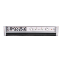
Parts List (Non-Module)

Module Information

Fuse and Display Module Parts List

Q43354-2 Output Module Parts List

Q43328-6 Main Module Parts List

Q43328-6 Main Module Parts List Continued

Q43399-7 Main Module Parts List

Q43399-7 Main Module Parts List Continued

Related product manuals