Do you have a question about the Crown CL1 and is the answer not in the manual?
Guidance on inspecting the new amplifier for transit damage and saving packing materials.
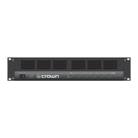
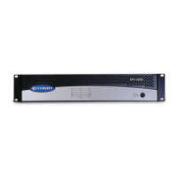
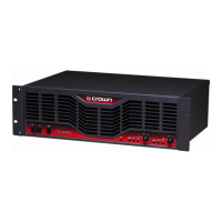
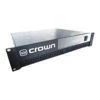
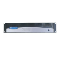
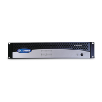
Highlights key features of Contractor Series amplifiers, including CH and CL series capabilities and warranty.
Details on rack mounting Contractor Series amplifiers, including dimensions and airflow considerations.
Explains how to wire amplifiers for different configurations including Stereo/Bridge modes and output operations.
Essential precautions to ensure optimal performance and safety during amplifier operation.
Step-by-step guide for safely turning on and operating the amplifier for the first time.
Explanation of the front panel indicators (Power, Signal, Clip, Fault) and their meanings.
Details on front and back panel controls including Enable switch, level controls, and mode switches.
Explanation of Crown's patented Balanced Current Amplifier technology for CH4 and CL4 models.
Overview of the benefits of the switching power supply with Power Factor Correction for CH4 and CL4 models.
Description of optional System Solution Topologies modules to enhance fidelity and versatility.
Details on using the RJ11 Fault jack to remotely monitor the amplifier's fault status.
Information on Crown's Constant Voltage Computer slide rule for audio applications.
Detailed explanation of the audio signal path and operation for CH1, CH2, CL1, and CL2 amplifier models.
Description of the audio signal path for CH4 and CL4 amplifier models, including filter and modulator stages.
Guidance on understanding and ensuring proper cooling for Contractor Series amplifiers.
Instructions and recommendations for connecting balanced and unbalanced audio input signals.
Explanation of 4/8 ohm and 70V/100V output modes, including load impedance considerations.
Guidance on selecting appropriate speaker cables and using the wire size nomograph for proper output wiring.
Instructions for setting up a circuit to use an LED to indicate amplifier fault status.
Example of a restaurant sound system setup using CH1, CL2, and CL4 amplifiers.
Example of a house of worship sound system setup utilizing CH1, CL2, and CL4 amplifiers.
Information on obtaining service from authorized service centers globally and shipping instructions.
Details on obtaining service through North American service centers or directly from the factory.
Overview of Crown's advance-replacement Profit Protection Plan for Contractor Series amplifiers.
| Cooling | Convection |
|---|---|
| Frequency Response | 20Hz - 20kHz, +0/-1 dB |
| Total Harmonic Distortion | <0.5% |
| Signal-to-Noise Ratio | >100 dB |
| Input Impedance | 20k Ohm |