Operation Manual
CT Power Amplifiers
page 10 page 11
CT Power Amplifiers
Operation Manual
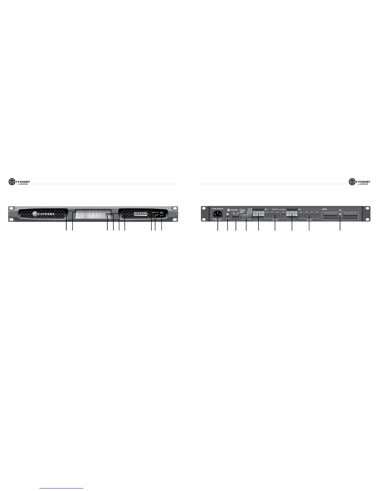
6 Front Panel
1. Fault Indicator
• Red LED
• One per output channel
• Flashes when the amplier output channel has
stopped operating. Usually this means that the
amplifier must be serviced. (See Section 15
Troubleshooting)
2. Thermal Indicator
• Red LED
• One per output channel
• If exceeds Thermal Limits, output channels will
shut down in pairs until thermal levels are within
tolerant ranges.
• Illuminates when the channel approaches
temperature constraints or is about to shut
down. Audible distortion may be heard.
• Unit stops amplication for each channel until
temperature returns to acceptable level. Once
the amp cools off enough, led turns off, audio
starts again.
3. Clip Indicator
• Red LED
• One per output channel
• Illuminates when the channel is at the threshold
of audible distortion (See Section 15
Troubleshooting – reduce input level)
• When the limiter is turned on the Clip Indicator
will illuminate when the limiter is protecting the
amplifier from input overload.
4. Signal Indicator
• Green LED
• One per input channel
• Illuminates when the input signal exceeds
-24dBu
5. Ready Indicator
• Green LED
• One per input channel
• Illuminates when the channel is ready for signal
• Illuminates when the channel is initialized and
ready to produce audio output.
• Ready indicator will ash when the channel
is in standby.
• Ready Indictor will not illuminate or ash when
the amplifier is in deep sleep.
6. Power Indicator
• Blue LED
• Indicates AC power has been applied and is
within the safe operating range of the power
supply. The LED will flash when the AC line
voltage is above or below the nominal rated
value. The LED will also flash when the
amplifier is in Deep Sleep mode AND the power
button has been pushed.
7. Data Indicator
• Yellow LED (not functional in analog version)
• Indicates network activity
• Reserved for future releases (Lite and DSP)
8. Power Button
• On/off push button
9. Cooling Vent
• Allows for air ow and cooling of the amplier
12 34
789
7 Back Panel
1. AC Power Inlet
• Standard IEC type 320 inlet for detachable
connector
• 100-240V
2. Reset Button/Breaker
• Push button switch
• Resets the circuit breaker that protects the power
supply
• A circuit breaker located near the IEC power inlet
protects the amplifier from excessive AC current
draw.
3. Auxiliary Connector
• 3-pin Phoenix type connector
• Allows for amp to be placed in DEEP SLEEP
mode and monitoring of AMP STATUS
(see Section 10.2)
4. Amp Configuration DIP Switches (see Amp
Status/Configuration in section 10.2)
• Switches 1-5 turn specic settings on and off:
-70 Hz HPF (High Pass Filter
- see Section 8.1)
-Auto-Standby
-Amp Status
-Green Power (See Section 9.2)
-Limiter
• Switches 6-12 sends input channel audio signal
to corresponding output channel and adjacent
output channel. In four channel model, switch
6-9 are non-functional, (see section 11)
5. Amp Input Connectors
• 3-pin block connector can be used per input
• High impedance balanced
6. Channel Level Controls
• One 21-position detented rotary attenuator per
channel
• Attenuation range from -100dB to 0dB
7. Output Speaker Connector
• 4-pin Barrier block type per two channels
(2-Pin or 8-Pin Phoenix can be used)
1234 56 75 6